Basic units in the power range 0.25 ... 2.2 kW
Connection of motor/external brake resistor
6
Basic unit wiring
6.4
6.4.4
L
6.4-6
EDS82EV903-1.0-11/2002
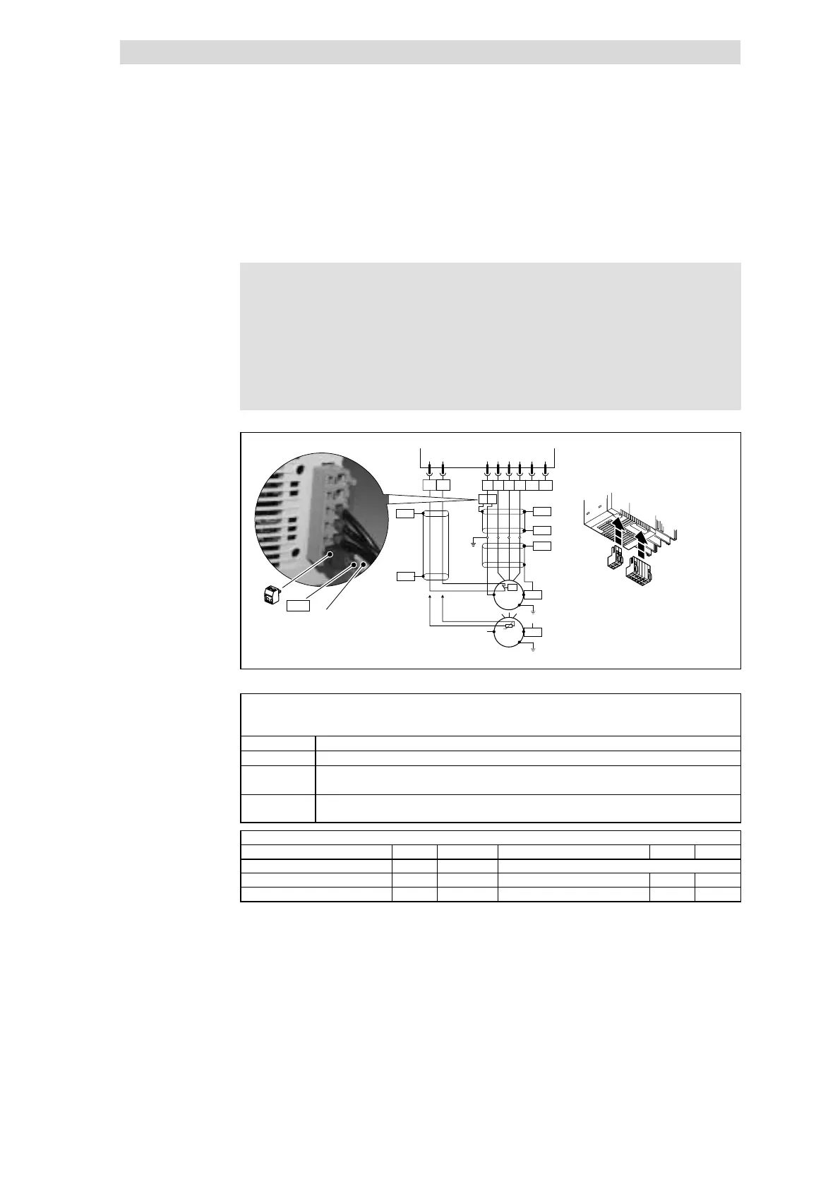
6.4.4 Connection of motor/external brake resistor
{ Danger!
l After the connection of a PTC thermistor or thermal contact all
control terminals only have a basic insulation (single insulating
distance).
l Protection against contact in the event of a defective insulating
distance can only be ensured by external measures (e.g.
double insulation).
1
2
X2.1
T
2
T
1
X2.2
PE
PES
W V
U
BR2 BR1
PE
PE
PE
X2.1
PES
PES
PES
PES
T1 T2
M
3~
X2.2
ϑ>
PES
M
3~
PTC
8200 vector
}
PES
PES
PE
68200vec009
Fig. 6.4-4 Motor connection 0.25 ... 2.2 kW
Use low-capacity motor cables! (core/core up to 1.5 mm
2
≤ 75 pF/m; from 2.5 mm
2
≤ 100 pF/m; core/shield
≤ 150 pF/m)
The shorter the motor cables, the better the drive response!
PES HF-shield end by PE connection through shield bracket or EMC cable connection.
X2.1/PE Earthing of the 8200 vector at the output side
X2.1/BR1,
X2.1/BR2
Connection terminals for the brake resistor
(For information about the operation with brake resistor see the Operating Instructions)
X2.2/T1,
X2.2/T2
Connection terminals motor temperature monitoring through PTC thermistors or thermal contacts
Activate motor temperature monitoring under C0119 (e. g. C0119 = 1)!
Cable cross-sections U, V, W, PE
Type mm
2
AWG Type mm
2
AWG
E82EV251K2C / E82EV371K2C 1 18
E82EV551K2C / E82EV751K2C 1 18 E82EV551K4C / E82EV751K4C 1 18
E82EV152K2C / E82EV222K2C 1.5 16 E82EV152K4C / E82EV222K4C 1.5 16
8200 vector 0.25 ... 2.2 kW
 Loading...