Braking operation
Operation with spring-applied brake
Introduction
7
101
EDS84DG752 EN 5.0
7.3 Operation with spring-applied brake
7.3.1 Introduction
Lenze three-phase AC motors and G-motion geared motors can be equipped with
spring-applied brakes (motor holding brakes). 8400 motec controllers are provided with
an integrated motor brake control.
Switching the brake
The voltage required for controlling the motor brake is generated in the controller,
depending on the mains voltage value. The following motor brakes can be connected:
ƒ With 400-V mains: Coil voltage 180 V DC
ƒ With 480-V mains: Coil voltage 215 V DC
Optionally, the switching of the brake can be controlled in addition:
ƒ Via an external control contact (e.g. PLC)
ƒ Via a brake switch which is connected to one of the digital outputs of the controller.
The digital output must be parameterised accordingly.
The software manual provides further information on the parameterisation and
integrated brake management.
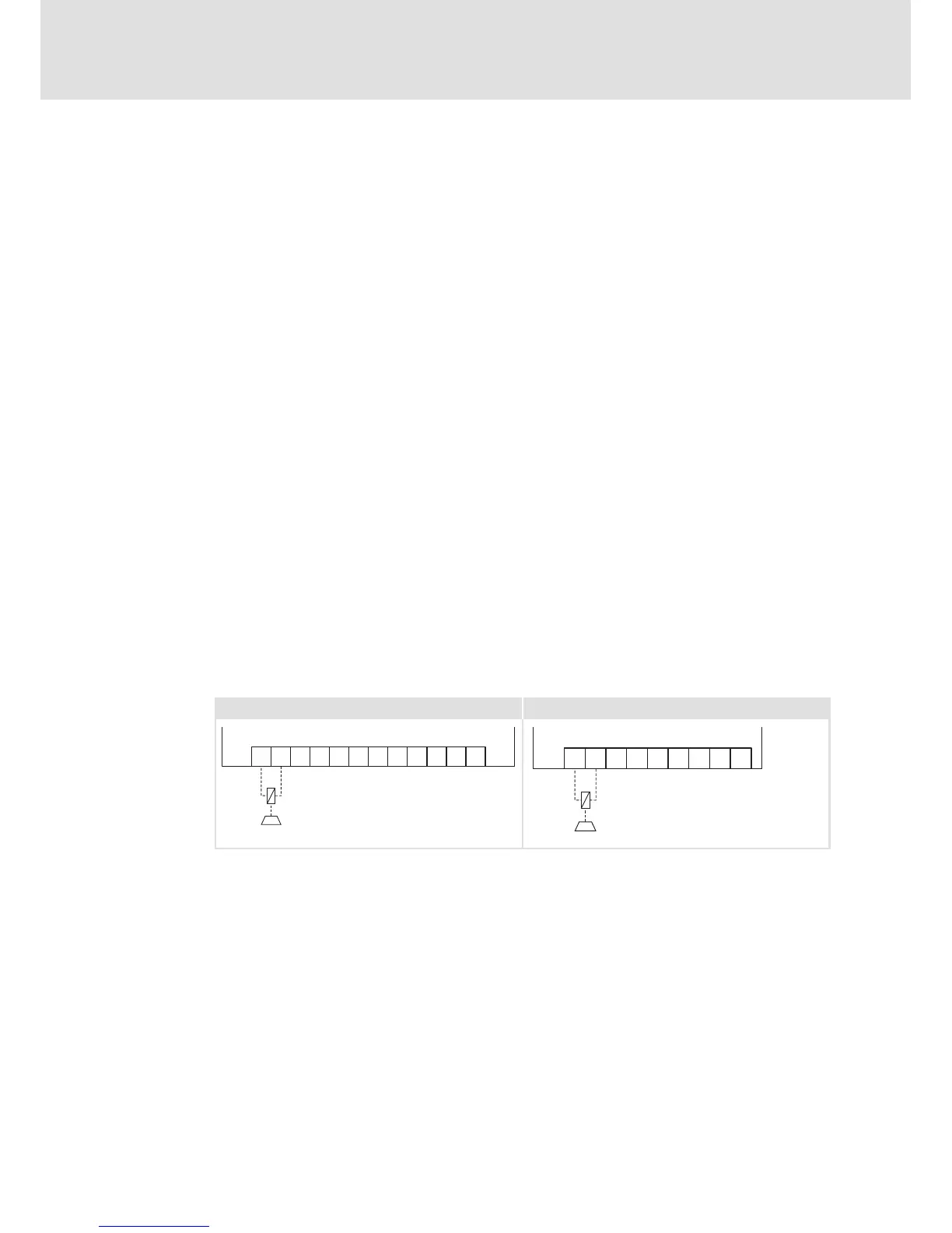
7.3.2 Wiring
The cable of the motor holding brake can be routed directly by means of a cable gland in
parallel to the motor axis.
The motor holding brake is connected to BD1 (+) and BD2 (-).
0.37 ... 3 kW 4 ... 7.5 kW
X1
BD1BD2 L1 L2
L3
Rb1Rb2
U
VW
T2 T1BD1BD2
+
-
X2
BD1BD2
Rb1Rb2
U
VW
T2T1BD1BD2
+
-
E84DG040 BD E84DG078
X1 Terminal in the Wiring Unit for devices 0.37 ... 3 kW
X2 Terminal in the Wiring Unit for devices 4 ... 7.5 kW
BD1 Connection of spring -applied brake +
BD2 Connection of spring -applied brake -
HF-shield termination by large surface connection to PE.
Earthing (PE)
 Loading...
