Safety engineering
Technical data
8
108
EDS84DG752 EN 5.0
8.5 Technical data
Supply
The safe input and the output are isolated and designed for a low-voltage supply through
a safely separated power supply unit (SELV/PELV) of 24 V DC. PM-switching input signals
and test pulses 1 ms are permissible.
Active sensors are directly connected to X61.
Passive sensors are connected to X61 via a switching device. The switching device must
comply with the required performance level of the application.
There is no monitoring for short circuits.
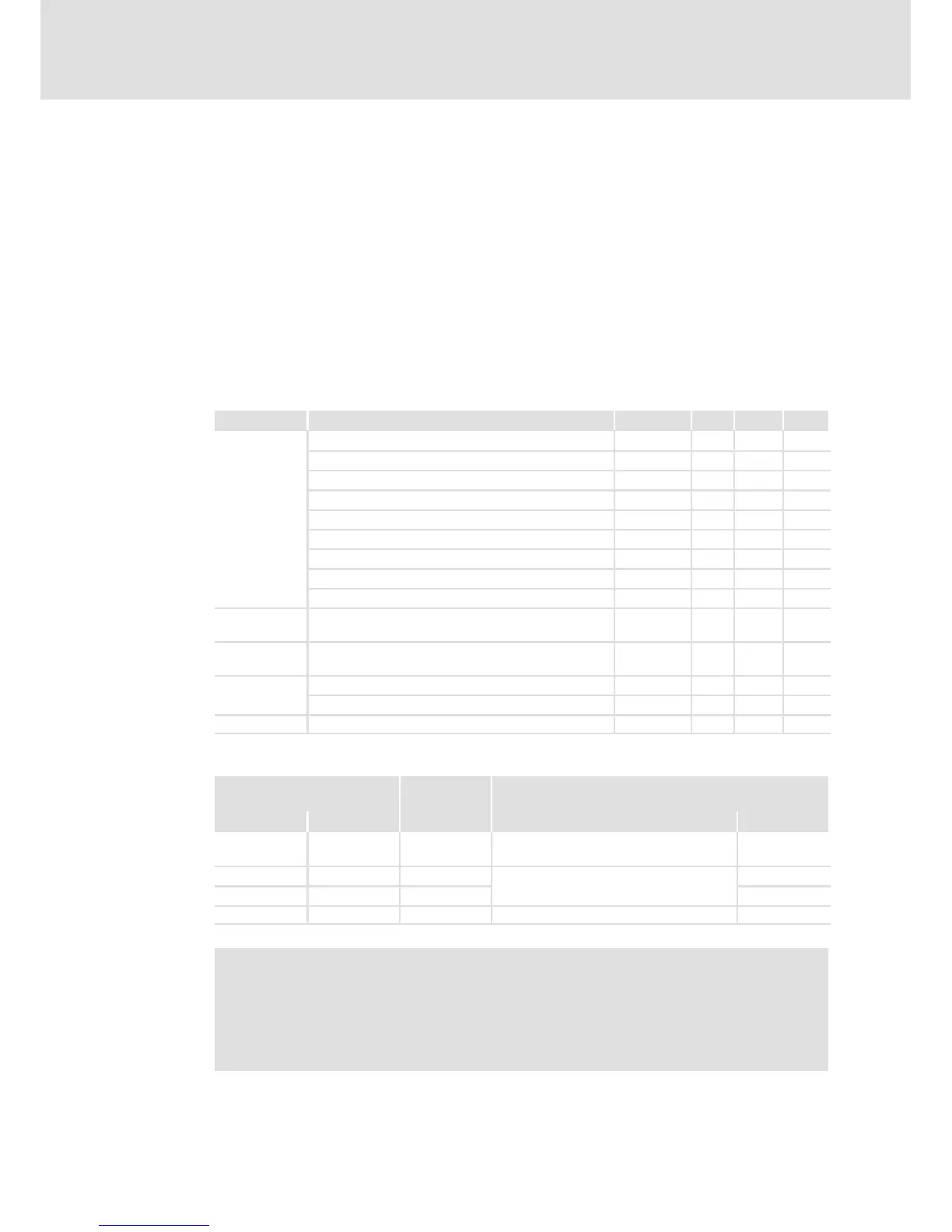
Detailed features of the inputs and outputs of the safety unit
Terminal Specification [Unit] min. typ. max.
SIA, SIB
Low signal
V -3 0 5
High signal V 18 24 30
Input capacitance at switch-off nF 3
Input delay (tolerated test pulse) ms 1
Switch-off time (depending on the controller) ms 2.5 4
Running time ms 3
Input current SIA mA 35 50
Input current SIB mA 25 50
Input capacitance at switch-on F 6
GI GND potential for SIA / SIB and for the unsafe
signalling output
24O Supply voltage through safely separated power supply
unit (SELV/PELV)
V 18 24 30
DO
Low signal V 0 0.8
High signal V 18 24 30
24O, DO Output current A 0.2
Truth table
Safe input / channel Signalling
output
Controller
SIA SIB DO Description of the device status Enable
001
”SafeTorqueOff” activated
(safe torque off)
0
0 1 0
Fault scenario or impermissible status
0
1 0 0 0
1 1 0 Drive active or ”ReadyToSwitchOn” 1
Note!
Safe inputs are designed with 2 channels (...A/...B). The channels must be
controlled separately and simultaneously (in an equivalent manner).
The active control of only one channel indicates a faulty sensor system or an
impermissible interconnection.
 Loading...
