Installation
Installation of 8400 motec pre-assembled on the motor
Attaching the cable gland
5
67
EDS84DG752 EN 5.0
5.7.2 Attaching the cable gland
0.37 ... 3 kW
Inorderto beableto screwthe c able glandsin theWiring Unitandconnect themains cable,
you must first dismount the Drive Unit and the Communication Unit as follows:
1. Loosen the four (captive) fixing screws of the motor inverter.
2. Remove the Drive Unit from the Communication Unit without twisting it.
3. Remove the already wired Communication Unit from plug-in connections or provide
for sufficient free moving space of an available cable harness.
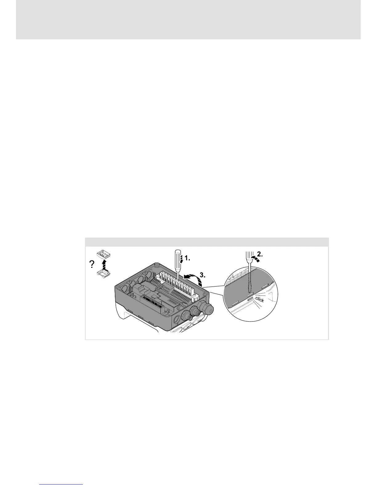
4. Unlock the Communication Unit (see fig. below). Remove the Communication Unit
and position it such that the Wiring Unit can be freely accessed for wiring.
5. Unscrew screw-type blank cap and replace by cable gland. Restore the sealing
requirements.
6. Insert mains cable and wire with L1 ... L3 and the earth connection .
– The same procedure applies to a subsequent connection of another mains cable
for loop-through or a cable for an external brake resistor.
– For an installation of the controller conforming to standards, the second earth
connection can be used for an additional equipotential bonding.
7. Mount the Communication Unit and the Drive Unit in reversed order of the
described steps.
0.37 … 3 kW
E84DG048
 Loading...
