Commissioning
Quick commissioning
General configuration settings
6
79
EDS84DG752 EN 5.0
6.2.1 General configuration settings
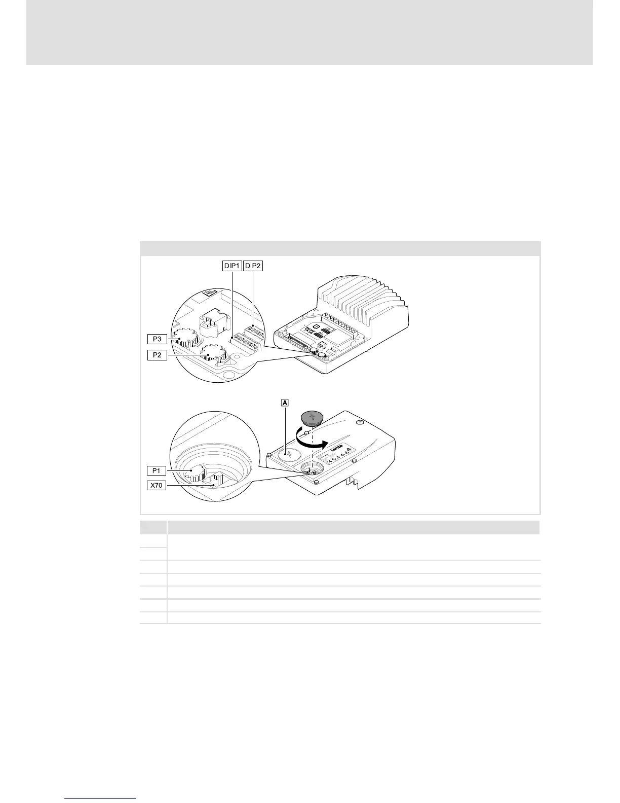
For initial commissioning, settings can be made via DIP switch and potentiometer. The
settings must be made before mounting the drive unit since the setting elements cannot
be accessed from the outside.
Setting elements 0.37 ... 3 kW
Thesettingelementsarelocatedontheinnersideofthedriveunit.
Settings carried out via DIP1, DIP2, P2, P3, and P1 must be activated with DIP1/1. The
settingsare acceptedagain at everymains connection. Thus, changes on parametersmade
in the meantime may be overwritten.
0.37 ... 3 kW
E84DG041
E84DG044
Name
DIP1
Switch for basic setting of quick commissioning
DIP2
P1 Setting ”Top Cover: Speed ... %”
P2 Setting ”Speed ... %”, (speed)
P3 Setting ”Ramp ... s”, (acceleration/deceleration time)
X70 Connection for USB diagnostic adapter E94AZCUS or diagnosis terminal
LED status display
 Loading...
