4. Device Concept MMX4x2 series – User's Manual 36
GPIO Interface
DIFFERENCE:
matrix switcher or third-party devices and peripherals. You can establish the connection between the
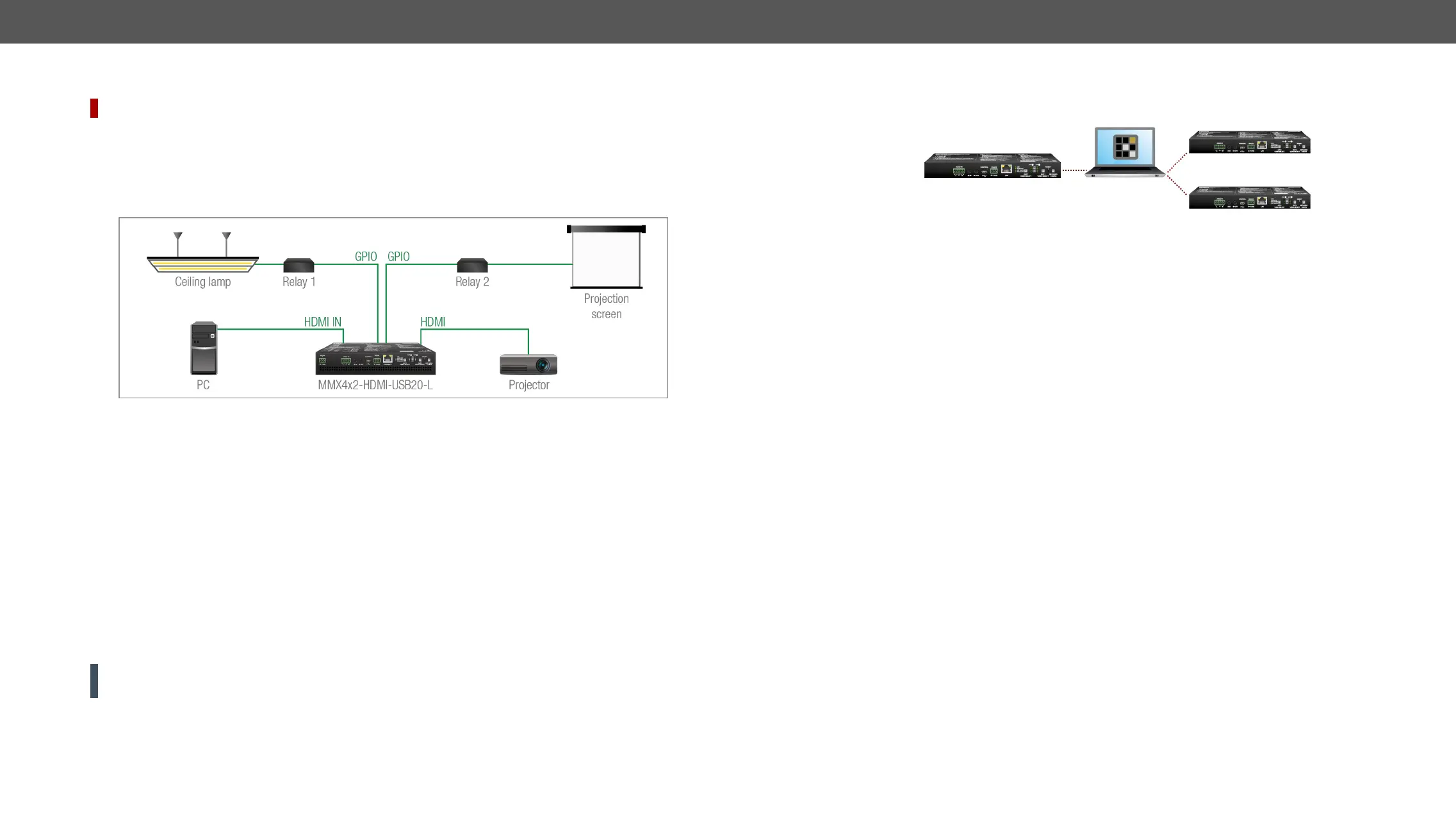
GPIO Options - Example
The Concept
The ceiling lamp is turned off by Relay 1 and the projection screen is rolled down by Relay 2 when signal is
received from the PC over the HDMI input. Both relays are controlled by the GPIO port.
Settings of the Transmitter
▪ For Relay 1: create an event in Event manager: when signal is present on Input 1 (I1), set the GPIO pins
to low level to open Relay 1. Also create another event: when signal is not present on Input 1 (I1), set
the GPIO pins to hight level to close Relay 1.
▪ For Relay 2: create an event in Event manager: when signal is present on Input 1 (I1), set the GPIO pins
to high level to close Relay 2. Also create another event: when signal is not present on Input 1 (I1), set
the GPIO pins to low level to open Relay 1
pins send a signal to Relay 1 to open, which turns off the lights. Furthermore, the GPIO pins also send a
ceases on the HDMI input, so the GPIO pins send a signal to Relay 1 to close, which turns on the lights, and
sends a signal to Relay 2 to open, so the projection screen returns to its enclosure.
ATTENTION! Please always check the electrical parameters of the devices that you want to control.
Please see the section for the details.
GPIO section. See the details about the Event Manager settings in
the Event Manager section.
Further Built-in Features
Restore section.
See more information about the settings in the section.
Advanced EDID Management
Factory Preset EDIDs
common resolutions. They are specially provided to force graphic cards to output only the exact pixel
resolution and refresh rate.
universal EDID is recommended for fast and easy system setup.
Sources and Destinations
The EDID memory consists of four parts:
▪ Factory EDID list shows the pre-programmed EDIDs (F1-F120).
▪ Dynamic EDID list shows the display device connected to the device's outputs. The unit stores the last
attached to the output port at the moment.
▪ User memory locations (U1 – U14) can be used to save custom EDIDs.
▪ Emulated EDID list shows the currently emulated EDID for the inputs. The source column displays the
memory location that the current EDID was routed from.
The source reads the EDID from the Emulated EDID memory on the INPUT port. Any EDID from any of the
There are two types of emulation: static and dynamic.
▪ Static EDID emulation: an EDID from the Factory or User EDID list is selected. Thus the Emulated EDID
remains the same until the user emulates another EDID.
▪ Dynamic EDID emulation
EDID is copied to the input; if a new monitor is attached to the output, the emulated EDID changes
automatically.
See more information about the settings in the EDID Menu section.
 Loading...