41
COMPILER TECO/ATL
REG. CODE
1-5302-296
MODEL N°
50510
DATE OF ISSUE
01.89
REVISION 02
ENDORSED
DATE
17.04.2003
93 94
95
96
VIII
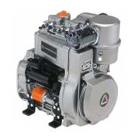
MECHANICAL SPEED GOVERNOR
The governor (with weights) is housed inside the crankcase and is
controlled by a camshaft gear. To remove speed governor 1 remove
camshaft bell 2 and speed governor control gear 3.
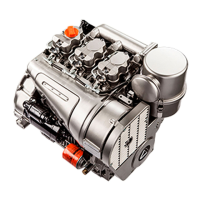
Mechanical speed governor components (standard)
1 Drive rod 2 Stop ring
3 Bearing 4 Washer
5 Pin 6 Weights
7 Weight support 8 Shaft
9 Key 10 Thrust washer
11 Bearings 12 Shaft support
13 Gear 14 Spring washer
15 Flat washer 16 Nut
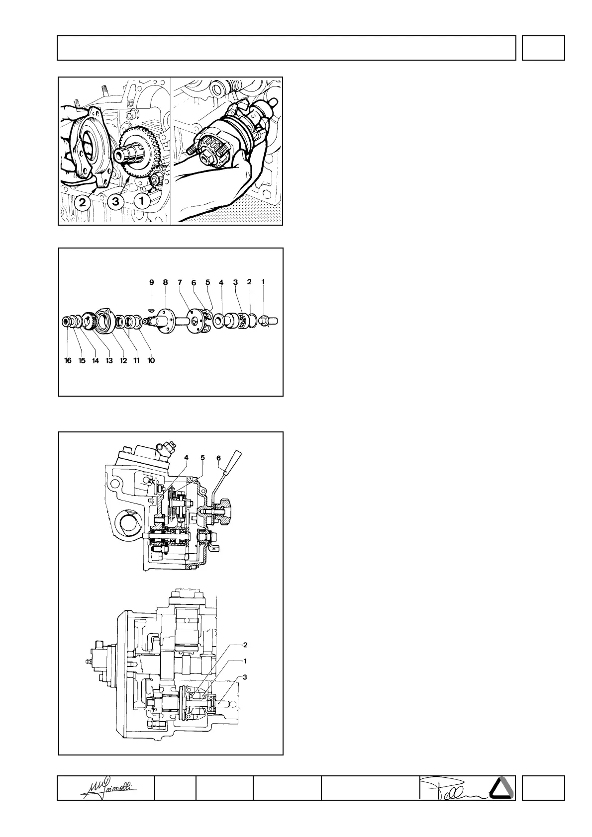
Mechanical speed governor operation (standard)
Weights 1 are moved to the periphery by the centrifugal force and
thus axially shift the washer 2 and the drive rod 3 which, by means
of a linkage, move injection pump control lever 4.
The governor springs 5 placed under tension by the accelerator
control lever 6 offset the weights 1 centrifugal force. Balance
between the two forces keeps speed at an almost constant level in
spite of load variations.
DISASSEMBLY/REASSEMBLY
 Loading...