53
COMPILER TECO/ATL
REG. CODE
1-5302-296
MODEL N°
50510
DATE OF ISSUE
01.89
REVISION 02
ENDORSED
DATE
17.04.2003
134
137
135 136
X
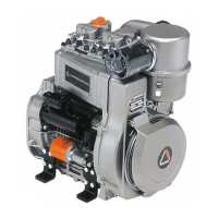
(STATIC) INJECTION TIMING
Disconnect injection line on cylinder 1 making sure not to loosen the
pump delivery union. Attach the timing tool shown below.
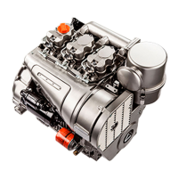
Injection timing checking device
Components:
1 Union
2 Tube
3 Sleeve
4 Transparent body, serial No. 7271-9727-003
This device allows for immediate monitoring of the fuel flow through
its transparent portion.
Dimensions (mm):
Ø1 =10.00; Ø2 = 0.60; Ø3 = 2.00; Ø4 = 6.50.
A = 29.00; B = 20.00; C = 25.00; D 45.00.
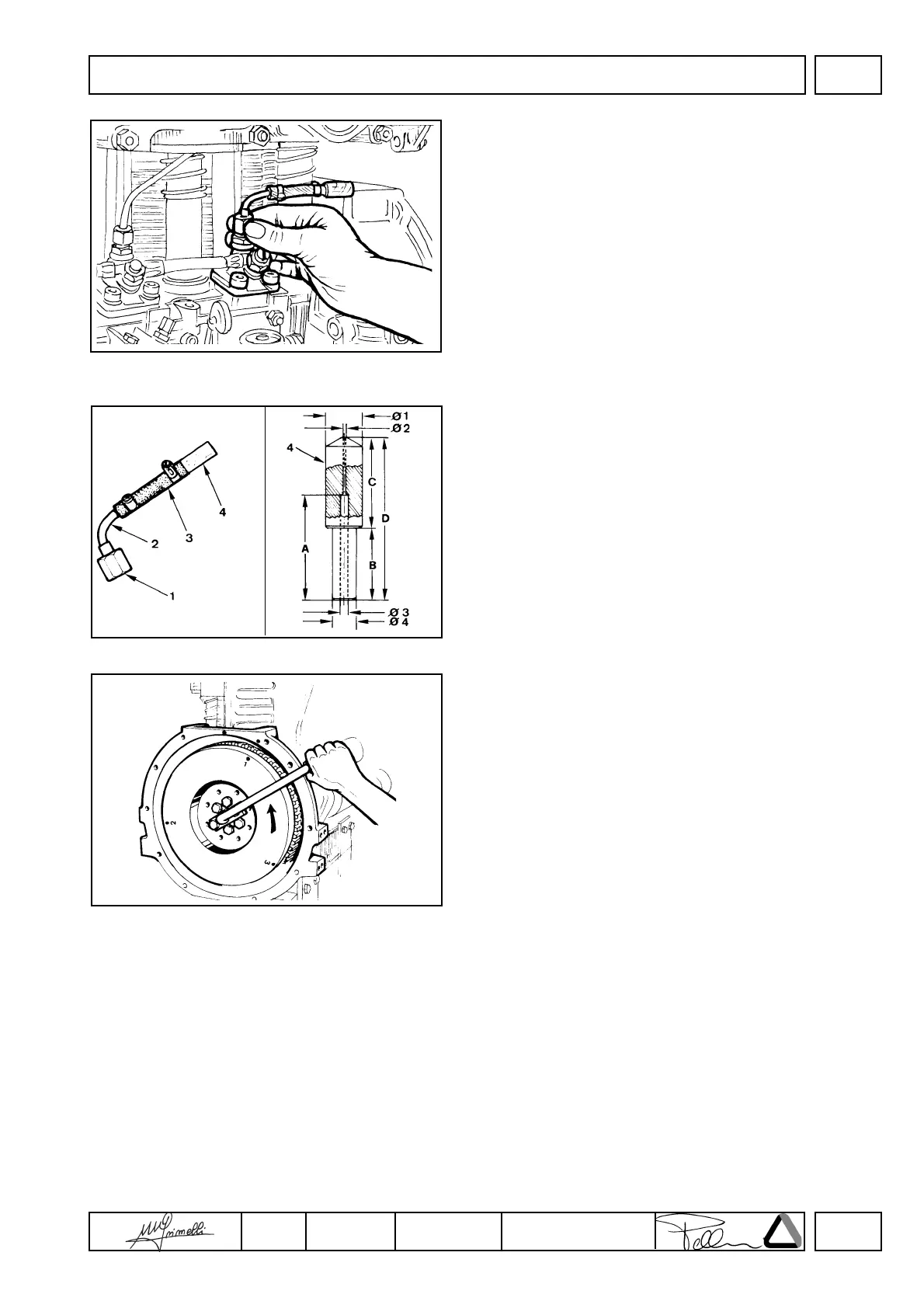
Injection timing check
Top up the tank checking that fuel level is at least 10 cm above
checking device.
Adjust injection pump rack rod at half-stroke.
Turn the flywheel according to the engine direction of rotation and
check that fuel reaches the checking device.
Repeat this last operation; during compression proceed slowly and
stop immediately when the fuel is seen to pass through the
checking device hole; bring flywheel back by 5 mm: This is the so-
called static injection timing.
Follow the same procedure for the other two pumps considering
that the flywheel has top dead center reference marks for each
cylinder marked with 1, 3 and 2 and staggered by 120°.
FUEL SYSTEM
 Loading...