55
COMPILER TECO/ATL
REG. CODE
1-5302-296
MODEL N°
50510
DATE OF ISSUE
01.89
REVISION 02
ENDORSED
DATE
17.04.2003
144
143
142
X
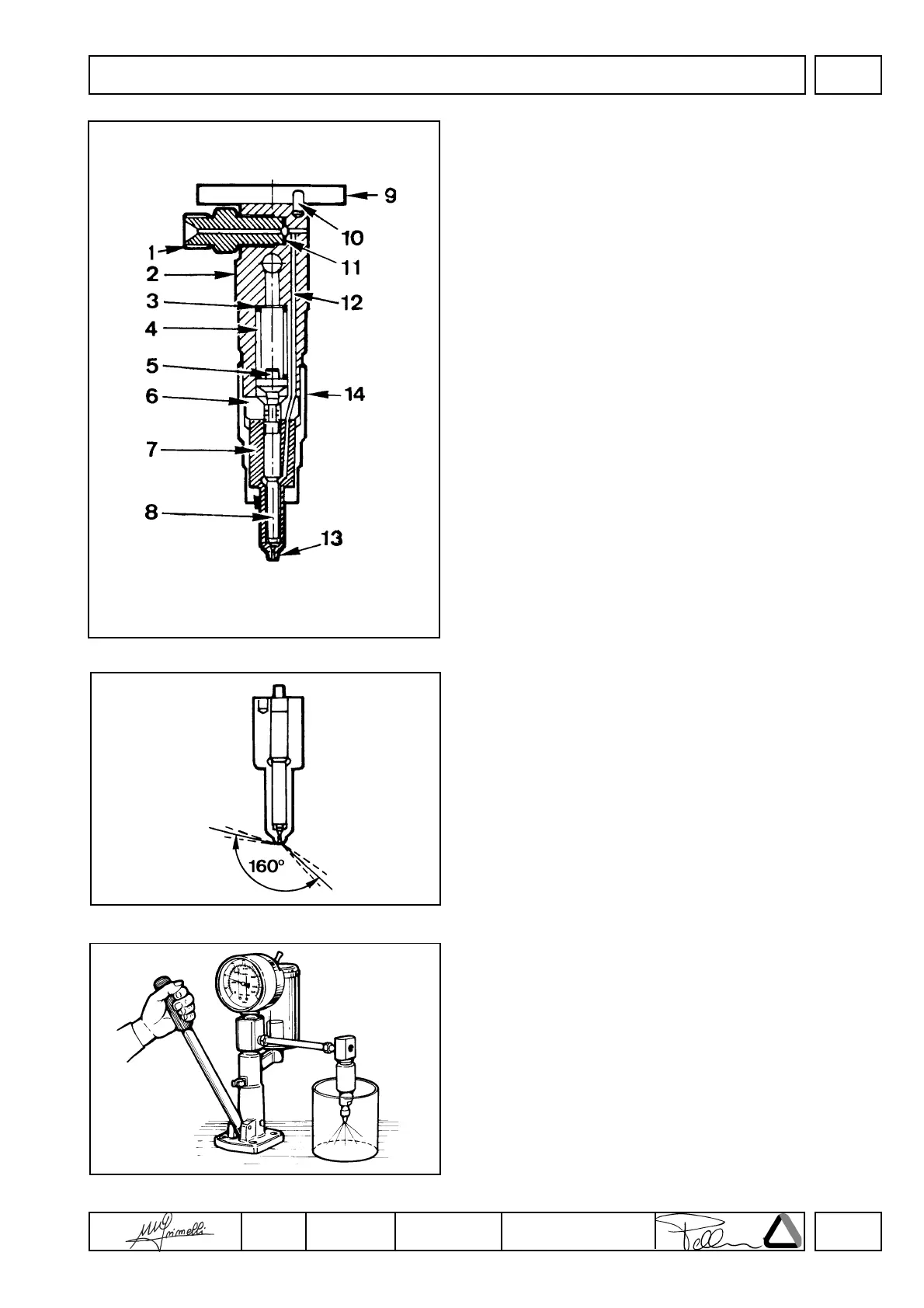
INJECTOR
Components:
1 Intake fitting
2 Nozzle holder
3 Shim
4 Spring
5 Pressure rod
6 Intermediate flange
7 Nozzle
8 Needle valve
9 Fixing flange
10 Taper pin
11 Gasket
12 System duct
13 Sump
14 Cup
Nozzle
Features:
Hole number and diameter 4x0.28 mm.
Jet angles = 160°.
Needle valve elevation = 0.20÷0.22 mm
Hole length = 0.7 mm
Sump diameter and length = 1x1.5 mm
Clean nozzle tip with a brass brush.
Check that holes are not obstructed using a mandrel with steel wìre
with 0.28 mm diam.
When refitting tighten ring nut at 7 Kgm.
Injector setting
Connect injector to a hand pump and check that setting pressure is
210÷220 bar; make the required adjustments, if any, by changing
the shim over the spring.
When replacing the spring, setting should be performed at a 10 bar
greater pressure (220÷230 bar) to allow for bedding during
operation. Check needIe valve sealing by slowly moving hand pump
until approximately 180 bar.
Replace nozzle in case of dripping.
FUEL SYSTEM
 Loading...