Connections
MXD75 Installation Guide
- 23 -
Connections
MXD75 Basic Connections
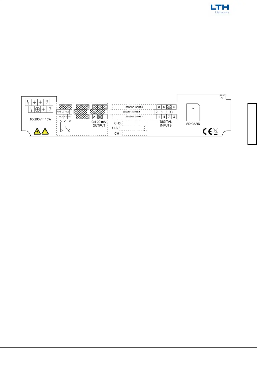
Having ensured that the main power is isolated from the instrument, remove the terminal
cover by releasing the three front screws. (The terminal cover is the small cover at the
bottom of the front panel). Once the cover has been removed the following terminal
arrangement should be visible. N.B. the appearance of the label will vary depending upon
which options are installed in the instrument.
MXD75 basic terminal label
The cables should be fed through the cable glands. After each cable has been attached,
pull most of the cable slack back through the cable gland to prevent any unwanted RF
energy from being radiated inside the housing. Make sure not to strain the cable within
the instrument. Tighten the cable gland onto the cable so that it grips sufficiently to seal
and to prevent the cable from being pulled back through the gland.

 Loading...