3-42
G - OCCASIONAL MAINTENANCE
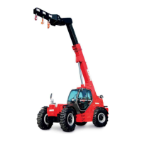
G1 - WHEEL
CHANGE
In the event of a wheel being changed on the public highway, make sure of the following points:
- Stop the lift truck, if possible on even and hard ground.
- To pass on stop of lift truck (see: 1 - OPERATING AND SAFETY INSTRUCTIONS: DRIVING
INSTRUCTIONS UNLADEN AND LADEN).
- Put the warning lights on.
- Immobilise the lift truck in both directions on the axle opposite to the wheel to be changed.
- Unlock the nuts of the wheel to be changed.
- Place the jack under the flared axle tube, as near as possible to the wheel and adjust the jack
(fig. G1/1).
- Lift the wheel until it comes off the ground and put in place the safety support under the axle
(fig. G1/2).
- Completely unscrew the wheel nuts and remove them.
- Free the wheel by reciprocating movements and roll it to the side.
- Slip the new wheel on the wheel hub.
- Refit the nuts by hand, if necessary grease them.
- Remove the safety support and lower the lift truck with the jack.
- Tighten the wheel nuts with a torque wrench (see: 3 - MAINTENANCE: A - DAILY OR EVERY 10
HOURS SERVICE for tightening torque).
NOTE: There is an OPTIONAL wheel toolkit and anti-puncture kit.
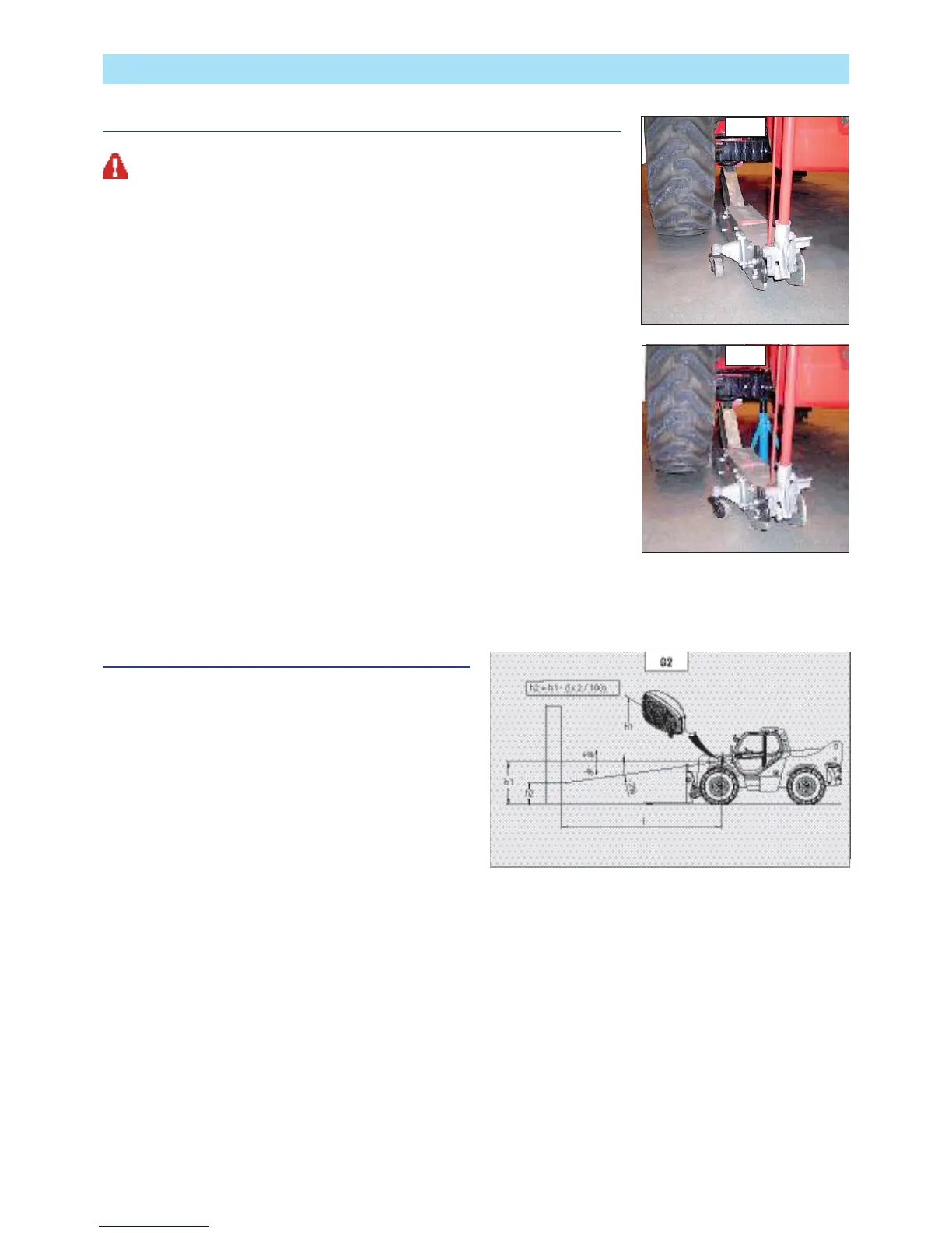
G2 - FRONT HEADLAMPS
ADJUST
RECOMMENDED SETTING
(as per standard ECE-76/756 76/761 ECE20)
Set to - 2% of the dipped beam in relation to the horizontal line of
the headlamp.
ADJUSTING PROCEDURE
- Place the lift truck unloaded and in the transport position and
perpendicular to a white wall on flat, level ground (fig. G2).
- Check the tyre pressures (see: 2 - DESCRIPTION:
CHARACTERISTICS).
- Place the forward/reverse selector in neutral and release the
parking brake.
CALCULATING THE HEIGHT OF THE DIPPED BEAM (H2)
• h1 = Height of the dipped beam in relation to the ground.
• h2 = Height of the adjusted beam.
• l = Distance between the dipped beam and the white wall.
G2/1
G2/2
G1/1
G1/2
 Loading...