1-15
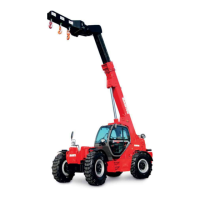
D - TRANSVERSE ATTITUDE OF THE LIFT TRUCK
Depending on the model of lift truck
The transverse attitude is the transverse slope of the chassis with respect to the horizontal.
Raising the jib reduces the lift truck’s lateral stability. The transverse attitude must be set with
the jib in down position as follows:
1 - LIFT TRUCK WITHOUT SLOPE CORRECTOR USED ON TYRES
- Position the lift truck so that the bubble in the level is between the two lines (see: 2 -
DESCRIPTION: INSTRUMENTS AND CONTROLS).
2 - LIFT TRUCK WITH SLOPE CORRECTOR USED ON TYRES
- Correct the slope using the hydraulic control and verify the horizontality via the level. The
bubble in the level must be between the two lines (see: 2 - DESCRIPTION: INSTRUMENTS AND CONTROLS).
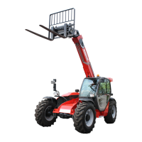
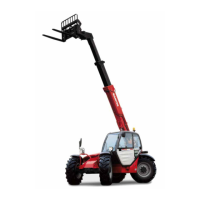
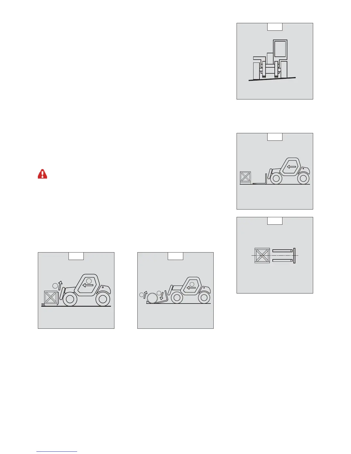
E - TAKING UP A LOAD ON THE GROUND
- Approach the lift truck perpendicular to the load, with the jib retracted and the forks in a
horizontal position (fig. E1).
- Adjust the fork spread and centering in connection with the load (fig. E2) (optional solutions
exist, consult your dealer).
- Never lift a load with a single fork.
Beware of the risks of trapping or squashing limbs when manually adjusting the forks.
- Move the lift truck forward slowly (1) and bring the forks to stop in front of the load (fig. E3), if
necessary, slightly lift the jib (2) while taking up the load.
- Bring the load into the transport position.
- Tilt the load far enough backwards to ensure stability (loss of load on braking or going downhill).
FOR A NON-PALLETIZED LOAD
- Tilt the carriage (1) forwards and move the lift truck slowly forwards (2), to insert the fork
under the load (fig. E4) (block the load if necessary).
- Continue to move the lift truck forwards (2) tilting the carriage (3) (fig. E4) backwards to
position the load on the forks and check the load’s longitudinal and lateral stability.
D1
E1
E2
1
2
E3
1
2
3
E4
 Loading...