2-35
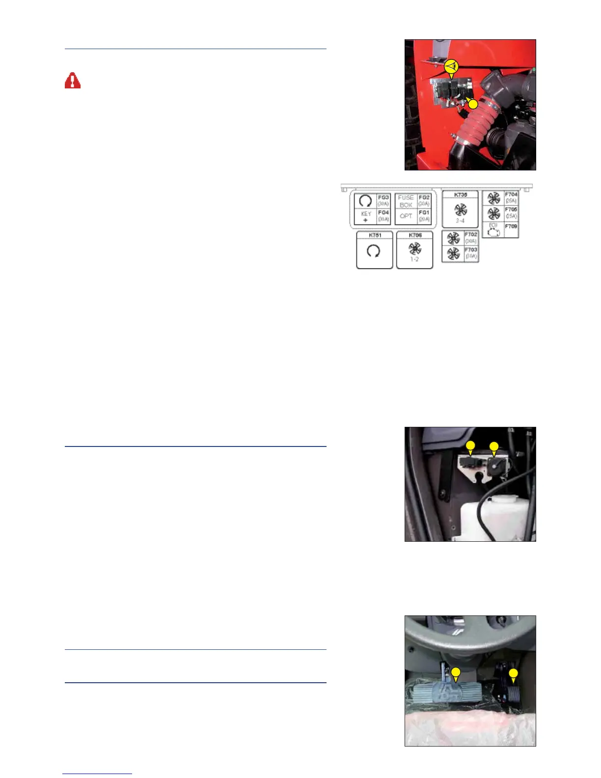
12 - FUSES AND RELAYS UNDER THE ENGINE HOOD
Remove casing 1 and cover 2 for access to fuses and relays.
Always replace a faulty fuse with another of equivalent rating. Never use a fuse that
has been repaired.
FG1 - OPTIONAL 30 (20A).
FG2 - Fuse and relay unit (30A)
FG3 - Start engine relay (30A).
FG4 - +30 key (30A)
F702 - Electric fan 1 (25A)
F703 - Electric Fan 2 (25A)
F704 - Electric Fan 3 (25A)
F705 - Electric Fan 4 (25A)
F709 - 30 Mercedes Unit
K706 - Electric Fan 1 and 2 Relays
K735 - Electric fans 3 and 4 Relays
K751 - Start engine Relay
13 - DIAGNOSTIC CONNECTOR
Remove the door that provides access to the diagnostic connector A.
A - Lift-truck electronic system
B - Mercedes electronic system
14 - ACCELERATOR PEDAL
15 - SERVICE BRAKE PEDAL AND TRANSMISSION CUT-OFF
The pedal applies on the front and rear wheels by an hydraulic brake system,
and allows the lift truck to be slowed down and stopped. Depending on the
position of the transmission cut-off switch, it enables the free travel to cut
off transmission (see: 2 - DESCRIPTION: 5 - SWITCHES).
12
14
15
B
A

 Loading...