3-44
G4 - BRAKE CYLINDER
CHECK
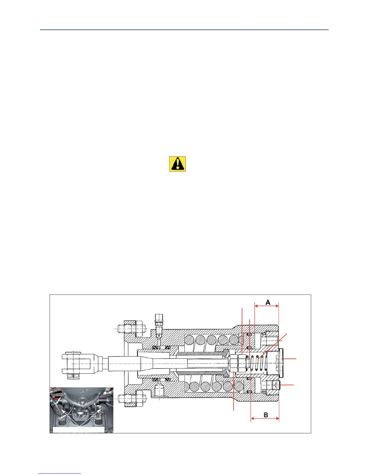
Brake cylinder (fig.G4)
- unscrew the caps “5”
- check that the dimension “A” is 29-29,5 mm if necessary screw the nut “1” until the piston reach that depht.
- unscrew the caps “4”
- take off the spring “7”
- with a key of 19 mm and external diameter not higher than 26 mm, unscrew the counter nut “9” and screw the nut “1”
till the piston is at a maximum depht of 29-29,5 mm (dimension “A”). The nut is “1” has a pitch of 1,75 mm so it’s possi-
ble to calculate how screw the nut, for example: if the dimension “A” is of 26 mm it’s necessary to screw it of 2 turns
(3,5 mm).
Check again the mesure as described and, if not right again, repeat the operations till now described.
- screw the counter nut “9” untill the nut “1”
- mount again the spring “7” and the caps “4” and “5”.
Note: exceeding the mesure of 29,5 mm the complete unlock of the brake it’s not possible, so the brake could overheat
and damage it self quickly.
A bad regulation could cause big damages to the brakes and also a quickly destruction.
If the nut “1” is unscrewed too far the machine doesn’t brake! Dangerous to your life!
Pay attention to the dimension “B” : if it’s lower than 21,5 mm you must change the brake disk.
FOR THESE OPERATION, CONSULT YOUR AGENT OR DEALER
Fig. G4
BRAKE CYLINDERS
1
9
8
5
4
7

 Loading...