FIGURE 3-10
3-115
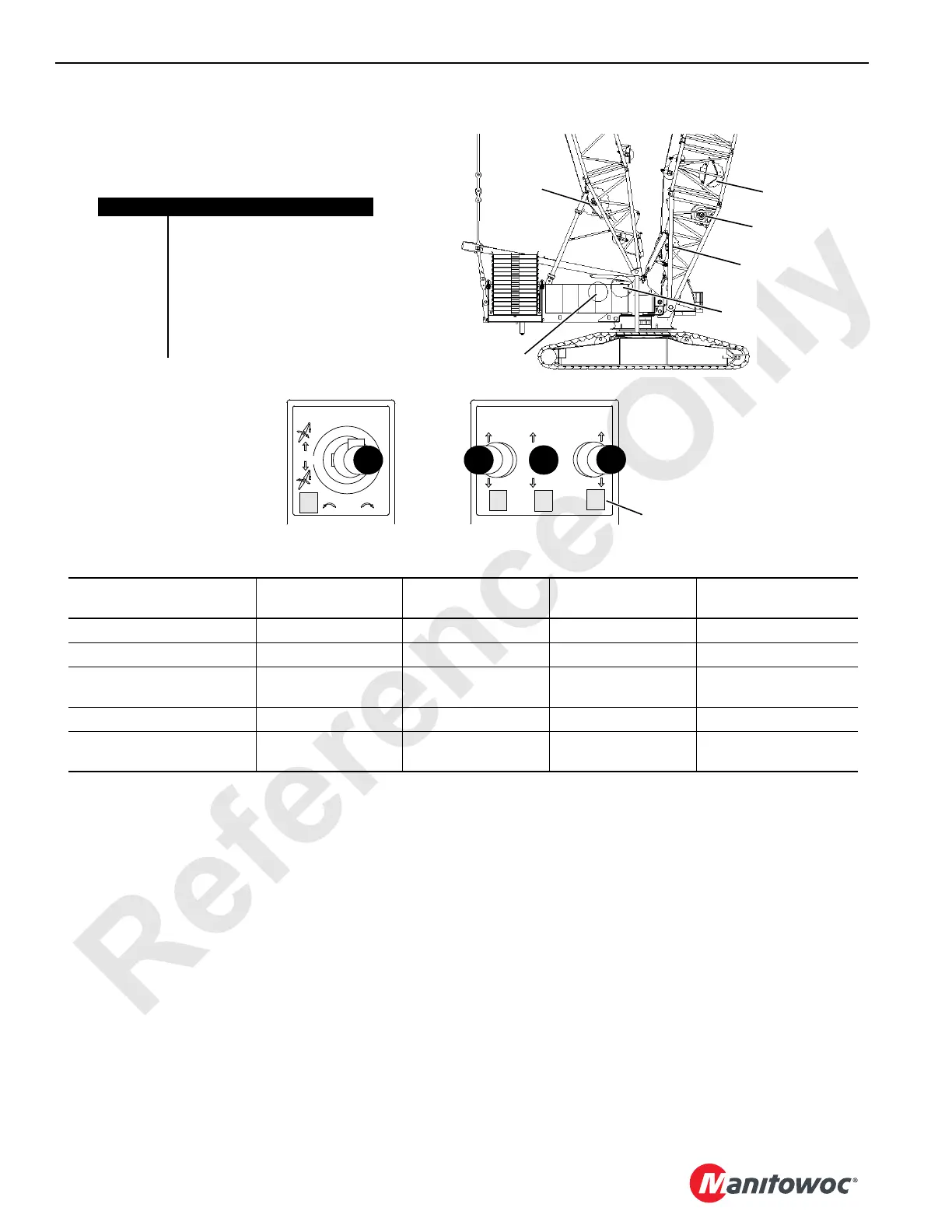
Item Description
1 Main Hoist 1 (in boom insert)
2 Main Hoist 2 (in boom butt)
3 Whip Line Hoist
4 Boom Hoist (in mast butt)
5Mast Hoist
6 Luffing Jib Hoist (in boom butt)
7 Rigging Winch (controlled by
radio remote switches)
DRUM AND HANDLE
IDENTIFICATION
Left Console
A
B
C
D
Mode Options (NOTE 1)
HANDLE A
Controls Drum
HANDLE B
Controls Drum
HANDLE C
Controls Drum
HANDLE D
Controls Drum
Standard (NOTE 2) 4 - Boom Hoist 1 - Main Hoist 1 2 - Main Hoist 2 3 - Whip Line Hoist
Setup (NOTE 2 and NOTE 3) 4 - Boom Hoist 3 - Whip Line Hoist 2 - Main Hoist 2 5 - Mast Hoist (NOTE 4)
Luffing Jib (NOTE 2) 6 - Luffing Jib Hoist 1 - Main Hoist 1
2 - Main Hoist 2
3 - Whip Line Hoist
4 - Boom Hoist
3 - Whip Line Hoist
Tandem Drum (NOTE 2) 4 - Boom Hoist 1 - Main Hoist 1 2 - Main Hoist 2 3 - Whip Line Hoist
Rigging Winch (NOTE 5) 7 - Rigging Winch 1 - Main Hoist 1 2 - Main Hoist 2
3 - Whip Line Hoist
6 - Luffing Jib Hoist
7
In Boom
Insert
NOTE 1: See handle display light to determine what drum is controlled by what handle.
NOTE 2: Main Hoist (Drum 1) and Whip Hoist (Drum 3) are both controlled by same pump. Only one drum
can be operated at a time. The drum operated first has priority over the other drum.
For cranes with software version M00200R.0SP or newer, while in Luffing Jib mode only, Whip
Hoist (Drum 3) will be assigned to Handle C and Boom Hoist (Drum 4) will be assigned to Handle
D when Main Hoist (Drum 2) is parked and Whip Hoist (Drum 3) is NOT parked.
NOTE 3: Main Hoist (Drum 2) and Mast Hoist (Drum 5) are both controlled by same pump. Only one drum
can be operated at a time.
NOTE 4: Mast Hoist 5 can be operated only in setup mode.
NOTE 5: See Section 4 of this manual for Rigging Winch Operation.
4
2
1
6
5
3
1
2
3
4
Handle Display Lights (4)
In Boom
Insert
Right Console
3-116

 Loading...


