GROVE 11-43
CD3340B/YB4411 STRUCTURAL
11
Published 04/07/2015 Control # 569-00
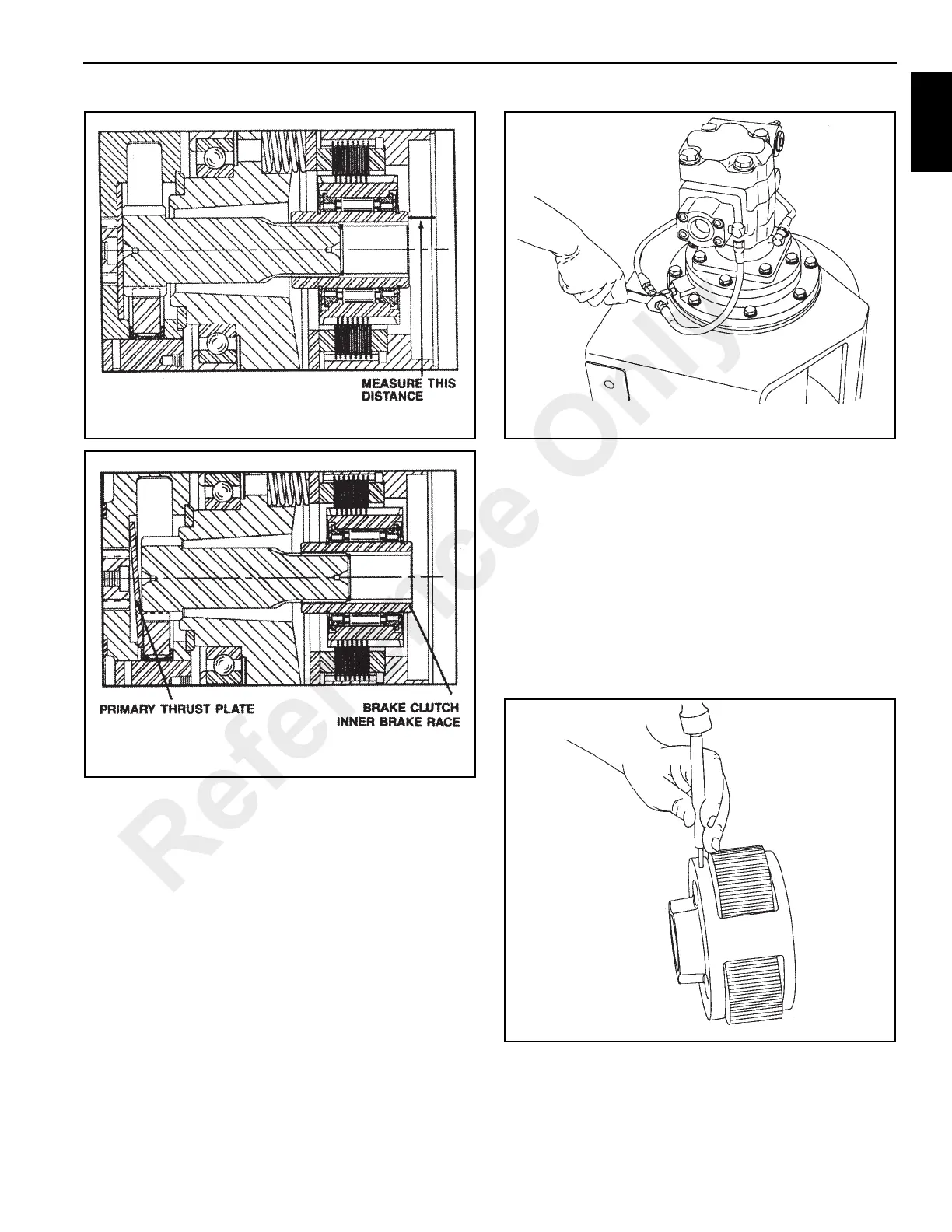
The Primary Thrust Plate is shown wedged between the
planet gears and the planet carrier. Note that the
Primary Sun Gear and the entire Brake Clutch Assembly
have moved to the right (toward the hydraulic motor).
18. Engage the motor shaft with the brake clutch inner race
and lower motor into place. Tighten capscrews to
recommended torque.
19. Install the hoses that connect the manifold and brake
valve to the brake cylinder (Figure 11-98).
20. After the hoist assembly is complete, check all
capscrews and fittings to make certain they have been
tightened correctly.
21. Refill the hoist with the recommended oil listed in
Section 5, and install the oil level plug.
Planet Carrier Service
Output Planet Carrier
Disassembly
1. Remove the planet gears by driving the roll pins into the
center of the planet shafts (Figure 11-99).
Reference Only

 Loading...


