STRUCTURAL CD3340B/YB4411
11-44
Published 04/07/2015 Control # 569-00
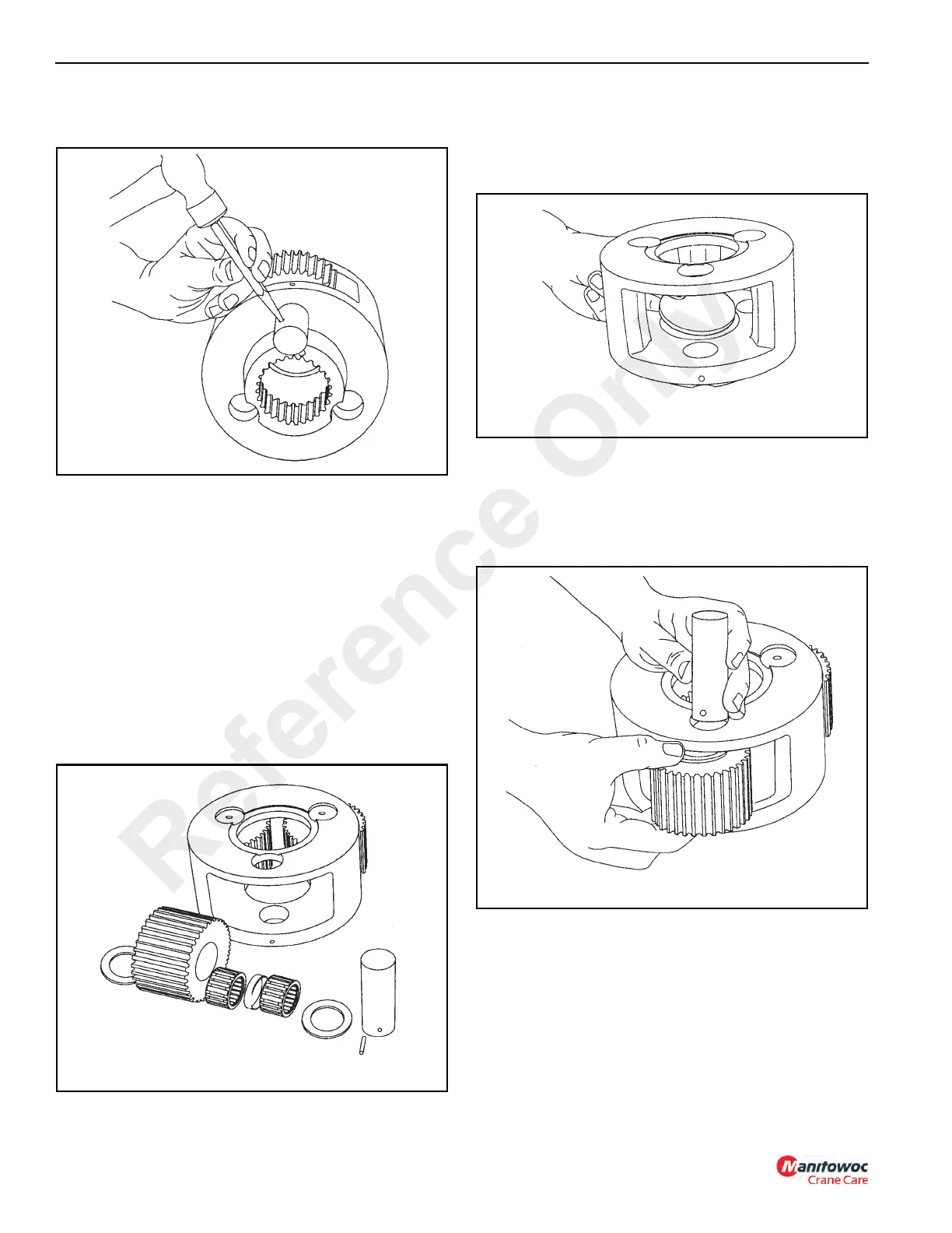
2. Use a punch (Figure 11-100) to drive the roll pins from
the planet shafts. Do not reuse the roll pins.
3. Now you can remove the planet shafts, bearings,
spacer, thrust washers and gears. Thoroughly clean all
parts and inspect for damage and wear. The bearing
rollers should not exhibit any irregularities. If the rollers
show any sign of spalling, corrosion, discoloration,
material displacement or abnormal wear, the bearing
should be replaced. Likewise, the cage should be
inspected for unusual wear or deformation, particularly
the cage bars. If there is any damage that will impair the
cage’s ability to separate, retain and guide the rollers
properly, the bearing should be replaced. The thrust
washer contact areas should be free from any surface
irregularities that may cause abrasions or friction. The
gears and shafts should be inspected for abnormal wear
or pitting. Replace if necessary.
Assembly
1. Place the output planet carrier on workbench with spline
coupling side down. Install output thrust plate in center
of carrier (Figure 11-102).
2. Insert two (2) bearings and a bearing spacer into a gear
with the spacer between the bearings. Place a thrust
washer on each side of the gear and position in a carrier
opening. Slide the shaft through the carrier, thrust
washer, bearing-gear subassembly and remaining thrust
washer (Figure 11-103).
3. Carefully align the pin hole in the carrier with the hole in
the planet gear shaft (Figure 11-104) and drive the roll
pin into place. Always use NEW roll pins. When properly
positioned, 50% of the roll pin will engage the planet
gear shaft and 50% will remain in the planet carrier.
Reference Only

 Loading...


