GROVE 4-19
CD3340B/YB4411 HYDRAULIC SYSTEM
Published 04/07/2015 Control # 569-00
increases pressure, counterclockwise reduces the
pressure.
6. Tighten the margin set screw.
7. Shut off the engine and disconnect the pressure gauge.
Pump Compensator Pressure Setting
The pump compensator pressure is the main hydraulic
system pressure. It is regulated by a pressure compensating
valve located on the main hydraulic pump.
NOTE: Always set the pressures on the pump
compensator and load sense relief valves together.
1. With the engine shut off, & pressure check diagnostic
quick disconnect (Parker PD240) with gauge still
installed on test nipple @ the G1 port (1, Figure 4-5).
2. On the control valve, remove the cap on the load sense
relief valve (1, Figure 4-7) loosen the jam nut and turn
the adjusting screw fully in.
3. Start the engine.
4. Ensure the boom is all the way down. Activate the boom
down function at full engine throttle. The pressure gauge
should read 276 +/- 3.5 bar (4000 +/- 50 psi).
5. If pressure reading is correct:
a. Shut off the engine, and disconnect the pressure
gauge.
b. Replace the cap nut on the load sense relief valve.
c. Set the pressure on the load sense relief valve, refer
to Load Sense Relief Valve Pressure Setting.
6. If pressure reading is incorrect:
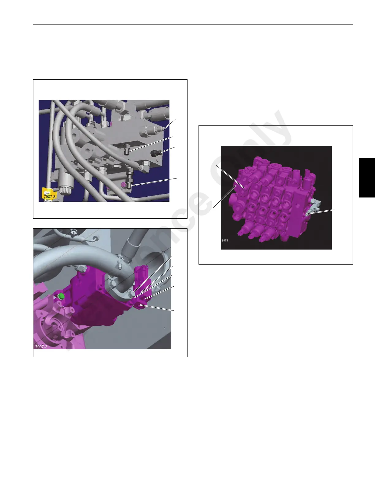
a. Remove the bolt on the suction hose split flange by
the compensator set screw (5, Figure 4-6).
b. Loosen the set screw from the pump compensator
valve (3, Figure 4-6).
c. While engaging the boom down function with the
engine at full throttle, adjust the pump max pressure
setting by turning the compensator adjusting screw
(2, Figure 4-6) until 276 ± 3.5 bar (4000 ± 50 psi)
pressure is obtained on the gauge; clockwise
increases pressure, counterclockwise reduces the
pressure.
d. Tighten compensator set screw.
e. Install and tighten the split flange bolt.
Reference Only

 Loading...


