HYDRAULIC SYSTEM CD3340B/YB4411
4-20
Published 04/07/2015 Control # 569-00
f. Shut off the engine, and disconnect the pressure
gauge.
Set the pressure on the load sense relief valve, refer to Load
Sense Relief Valve Pressure Setting
Load Sense Relief Valve Pressure Setting
NOTE: Always set the pressures on the pump
compensator and load sense relief valves together.
1. Install a 0 - 344.73 bar (0-5000 psi) pressure gauge on
the load sense test port GLS (2, Figure 4-5) located on
the front outrigger manifold.
2. Start Engine, ensure the boom is all the way down.
Activate the boom down function at full engine RPM,
gauge should read 238 ± 3.5 bar (3450 ± 50 psi), if the
pressure needs to be adjusted adjust the load sense
relief setting by turning the relief valve adjusting screw
(1, Figure 4-7) until 238 ± 3.5 bar (3450 ± 50 psi)
pressure is obtained on the pressure gauge; clockwise
increases pressure, counterclockwise reduces the
pressure.
3. Tighten the jam nut on the load sense relief valve.
4. Shut the engine off and disconnect the pressure gauge.
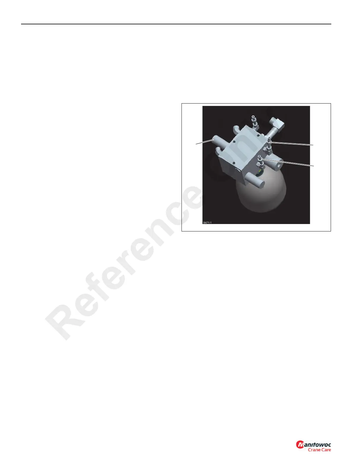
Priority Flow Load Sense Relief and Accumulator
Relief Setting
1. Install a 0 - 344.73 bar (0-5000 psi) pressure gauge on
the G1 port (1, Figure 4-8) located on the brake/steering
manifold.
2. With the park brake ON, start the engine. Set crane up
on a level surface with outrigger jacks fully extended.
3. With the engine at full RPM turn steering wheel all the
way to one side until the steer cylinder bottoms out
while another person adjusts the priority flow load sense
relief setting by turning the relief valve adjusting screw
(2, Figure 4-7) until 172 ± 3.5 bar (2500 ± 50 psi) is
obtained on the pressure gauge; clockwise increases
pressure, counterclockwise reduces the pressure.
4. Shut down the engine and remove the pressure gauge.
5. Install a 0 - 344.73 bar (0-5000 psi) pressure gauge on
the G2 port (3, Figure 4-8) located on the brake/steering
manifold.
6. With the engine at idle, repeatedly depress the service
brake pedal on the cab floor until the gauge pressure
reads approximately 117 bar (1700 psi). Once you have
found the pressure, push the brake pedal again to
recharge. Watch the gauge and verify the low charging
limit to be 110 +/- 7 bar (1600 +/- 100 psi) (when it starts
to recharge). Then watch gauge as valve is charging it
should cut out at 138 +7/-0 bar (2000 +100/-0 psi) if not
adjust at UP10 piloted unloading valve (2, Figure 4-8);
clockwise increases pressure, counterclockwise
reduces pressure. (Note: If charge valve does not cut
out check load sense relief valve pressure per Load
Sense Relief Valve Pressure Setting procedure).
7. Shut down the engine and remove the pressure gauge.
Outrigger Circuit Pressure Setting
1. Shut off the engine. Install a 0 - 344.73 bar (0-5000 psi)
pressure gauge to the front outrigger manifold test point
G2 (4, Figure 4-5).
2. Start and accelerate the engine to maximum RPM.
3. Actuate the outrigger enable switch to the extend
position while another person observes the pressure
gauge. The pressure should be 145 ± 3.5 bar (2100 psi ±
50 psi).
4. If the pressure reading is correct, stop the engine and
remove the pressure gauge.
5. If the pressure reading is incorrect:
a. Loosen the jam nut on the outrigger relief valve (3,
Figure 4-5) at the front of the machine on the front
outrigger housing weldment.
b. Adjust the outrigger circuit pressure by turning the
adjustment screw until 145 ± 3.5 bar (2100 psi ± 50
psi) is obtained on the pressure gauge; clockwise
increases pressure, counterclockwise reduces the
pressure.
c. Tighten the jam nut against the relief valve body.
d. Shut down the engine and remove the pressure
gauge.
Reference Only

 Loading...


