Grove Published 11-22-2016, Control # 345-12 3-3
RT9130E-2 SERVICE MANUAL ELECTRICAL SYSTEM
The following fuse assignments apply:
Fuse 51 (Figure 3-5) protects the charging circuit, fuse 52
protects the power relay in the battery box and line 5 to the
swivel.
Fuses 53, 54 and 55 are inside the battery box compartment
located behind the fuel tank on the left side of the crane.
These fuses protect the superstructure electrical power
system (Figure 3-5).
Fuse 56 is located inside the battery box compartment
behind the batteries on the left side of crane. This fuse
protects the Cummins engine electronic control module
(ECM) and carrier control module (CCM).
For machines with the retarder option, a 10A fuse in line 180
protects the retarder circuit parts.
Relays
NOTE: Refer to the electrical schematic in the back of this
manual for a diagram of the electrical system.
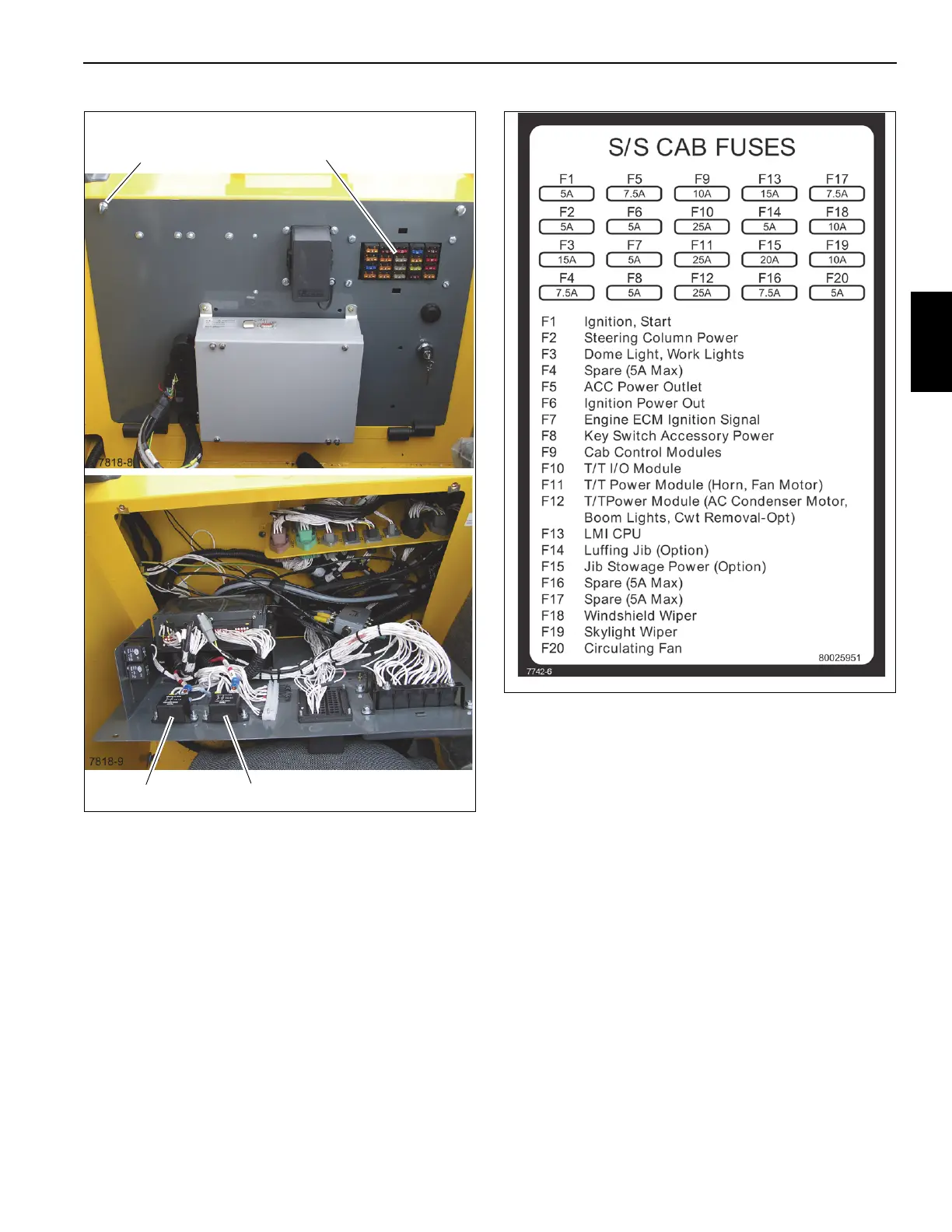
FIGURE 3-3
Fuse Panel
Thumb Screw
Relay and Fuse Panel
ACC #2
ACC #1

 Loading...


