Grove Published 11-22-2016, Control # 345-12 2-39
RT9130E-2 SERVICE MANUAL HYDRAULIC SYSTEM
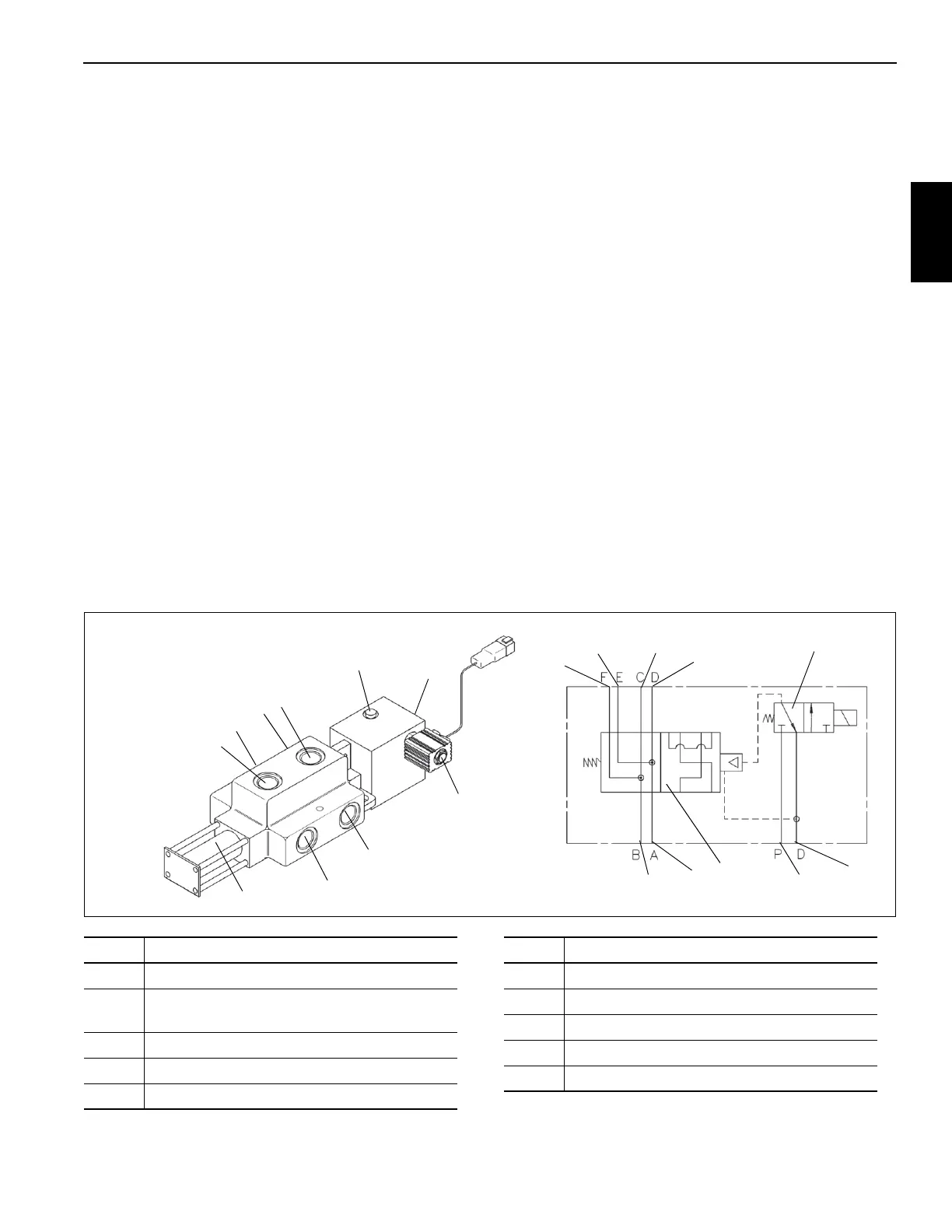
SWING SERIES PARALLEL SELECTOR
VALVE
Description
The series parallel selector valve Figure 2-21 is used to
select the swing motor speed. It is located on the outside of
the turntable right hand side plate. It consists of a pilot
operated two-position four-way valve (1) and a solenoid
actuated two position three-way (2) Figure 2-21 that is the
pilot valve. It is plumbed between the swing directional
control valve and the swing motors.
Swing speed is selected by the swing speed control switch
on the left-side of the console. In the de-energized position
or LOW SPEED switch position, the pilot operated two-
position three way solenoid vents the pilot operated four-way
valve to the tank leaving its spring return spool position
connecting the swing motors in parallel or low speed mode.
In the HIGH SPEED position, the pilot operated two-position
three-way solenoid valve is actuated and shifts the spool of
the operated two-position four-way valve which connects the
swing motors in series or high speed mode. The port reliefs
of the swing directional control valve are set to allow a full
load swing in both modes.
The 250 psi (1724 kPa) pilot pressure source is supplied via
the pressure reducing sequence with solenoid controls
manifold valve.
Maintenance
Removal
1. Tag and disconnect the electrical connector to the valve.
2. Tag and disconnect the hydraulic hoses from the valve.
Cap or plug the lines and ports.
3. Remove the two retaining screws securing the valve to
the turntable side plate.
4. Remove valve.
Installation
1. Secure the valve to the crane using the two retaining
screws.
2. Connect the hydraulic hoses to the ports on the valve as
tagged during removal.
3. Connect the electrical connector to the valve as tagged
during removal.
4. Verify proper operation of the valve. Refer to the
Operator’s Manual
5. Check valve and hydraulic connections for leaks. Make
repairs as needed.
FIGURE 2-21
3
4
1
2
5
6
7
8
1
2
3
4
5
6
7
8
9
10
9
10
Item Description
1 Pilot Operated Two-Position Four-Way Valve
2
Solenoid Actuated Two-Position Three-Way
Valve
3 Port “A” From Swing/Steer Directional Valve
4 Port “B” From Swing/Steer Directional Valve
5 Port “E” To Swing Motor
Item Description
6 Port “F” To Swing Motor
7Pilot Port
8Drain Port
9 Port “C” To Swing Motor
10 Port “D” To Swing Motor

 Loading...


