Grove Published 11-22-2016, Control # 345-12 2-21
RT9130E-2 SERVICE MANUAL HYDRAULIC SYSTEM
PRESSURE SETTING PROCEDURES
The following procedures should be used to properly check,
adjust and set the hydraulic system pressures.
The following equipment is required for checking the
hydraulic pressure settings.
• Three dial pressure gauge, 0-5000 psi
• Pressure check diagnostic quick disconnect - Grove P/N
9999101806 and straight adapter fitting 7447040401
• ORFS reducers as required to attach work port hoses to
the gauge.
NOTE: When checking directional control valve relief
settings, unless otherwise specified, start with the
engine at idle RPM and move the controller to its
fully stroked position. Then slowly accelerate the
engine to the specified RPM. Read gauge and
make adjustments to the specified setting.
When checking the outrigger relief valve setting,
start with the engine at idle RPM and activate and
hold the extend switch. Then slowly accelerate the
engine to the specified RPM. Read gauge and
make adjustment as required.
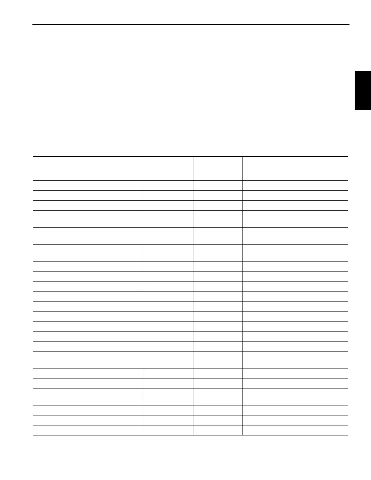
Table 2-3
Valve Pressure Setting Table
Valve To Be Set
Pressure
Setting PSI
(MPa)
Tolerance
PSI (MPa)
Adjustment Location
Max System Pressure 4000 (27.6) ± 50 (0.4) Main Valve Inlet Section
Telescope Inner Mid Retract 3500 (24.1) ± 50 (0.4) Main Valve Tele Inner Mid Retract Port
Tele Inner Mid Extend 3000 (20.7) ± 50 (0.4) Main Valve Tele Inner Mid Extend Port
Telescope Center/Outer Mid Retract 3500 (24.1) ± 50 (0.4) Main Valve Tele Center/Outer Mid
Retract Port
Tele Center Mid Extend 2500 (17.2) ± 50 (0.4) Main Valve Tele Center Mid Extend
Port
Tele Outer Mid Extend 3000 (20.7) ± 50 (0.4) Main Valve Tele Center/Outer Mid
Extend Port
Pressure Reducing Sequence 1200 (8.3) +50/-0 (+0.4/-0) Pressure Reducing Sequence Valve
Swing Brake Supply Pressure Reducing 250 (1.7) +50/-0 (+0.4/-0) Pressure Reducing Sequence Valve
Controller Supply Pressure Reducing 400 (2.7) ± 50 (0.4) Pressure Reducing Sequence Valve
Front Steer Relief Valve 2500 (17.2) ± 50 (0.4) Swing/Steer Control Valve
Swing "Left" Relief 2500 (17.2) ± 50 (0.4) Swing/Steer Control Valve
Swing "Right" Relief 2500 (17.2) ± 50 (0.4) Swing/Steer Control Valve
Outrigger Beam Extend 2000 (13.8) ± 50 (0.4) Outrigger/Rear Steer Valve Inlet
Outrigger Jack/Rear Steer/Pin Removal 3500 (24.2) ± 50 (0.4) Outrigger/Rear Steer Valve Inlet
Service Brake & A/C Relief 3000 (20.7) ± 50 (0.4) Service Brake & A/C Pump
Service Brake High Charge Limit
2490 (17.2)
+72/-145
(+0.5/-1.0)
Dual Accumulator Charge Valve
Service Brake Low Charge Limit 2100 (14.5) ±145 (1.0) Dual Accumulator Charge Valve
Accumulator Pre-charge 1400 (9.7) +50/-0 (+0.4/-0) Accumulator
Make-up Oil Manifold
200 (2.8) +0,-25 (0.2)
Make-up Manifold, Pressure Reducing
Valve
Charge Air Cooler Relief Valve 1700 (11.7) ± 50 (0.4) Charge Air Cooler Control Valve
Counterweight Removal Relief 3800 (26.2) ± 50 (0.4) Counterweight Removal Valve
Luffing Extension Lower Relief 1450 (10.0) ± 50 (0.4) Counterweight Removal Valve

 Loading...


