8-14 Published 11-22-2016, Control # 345-12
UNDERCARRIAGE RT9130E-2 SERVICE MANUAL
Bleeding the Brake System
The brake system should be bled whenever air becomes
entrapped within the brake system (usually characterized by
a spongy feeling during brake pedal application), whenever
any brake system line has been opened, or whenever any
brake component has been replaced.
Always start at the point in the system that is furthest from
the tandem brake valve and work back toward the tandem
brake valve. Bleed every bleeder screw on every caliper/
actuator on every wheel. When you complete a bleeder
screw, go to the next closest bleeder screw on the same
caliper/actuator. When you complete a wheel, go to the
furthest bleeder screw on the next closest wheel.
Service Brakes
Description
The brakes utilized are hydraulic disc-type brakes. Two
brake assemblies are used at the end of each axle. The
action of the brake pads riding against the brake discs acts to
slow the rotation of the wheels.
Maintenance
NOTE: To perform maintenance on the brake caliper,
remove the tire and wheel assembly. Refer to
Axles, page 8-1.
Removal
Linings
1. Remove the bolts securing the end plates to one side of
the caliper housing. Remove the end plates.
2. Loosen the bleeder screws to release hydraulic
pressure in the caliper (Figure 8-5).
3. Use a piece of wood against the linings as a pry bar to
push the pistons completely into the housing. Tighten
the bleeder screws.
4. Remove the linings from the caliper housing. If
necessary, discard the linings.
Caliper
NOTE: To lighten caliper weight, remove the brake linings
from the caliper before removing the caliper from
the vehicle.
1. Disconnect the hydraulic brake line from the inlet fitting
on the caliper. Cap or plug all openings.
2. Remove the linings as described previously.
3. Remove the bolts securing the caliper housing to the
mounting bracket. Remove the caliper housing from the
mounting bracket. If shims are used mark the position of
the shims.
Disassembly
Caliper
1. Remove the inlet fitting and o-ring from the cylinder cap.
2. Drain and discard the hydraulic fluid.
3. Clean the outside of the housing with isopropyl alcohol.
Dry the housing with a clean cloth.
4. If installed, remove the bolts that secure the end plates
to the housing. Remove the end plates and linings.
5. Remove the pistons from the side of the housing
opposite the mounting plate according to the following
procedure.
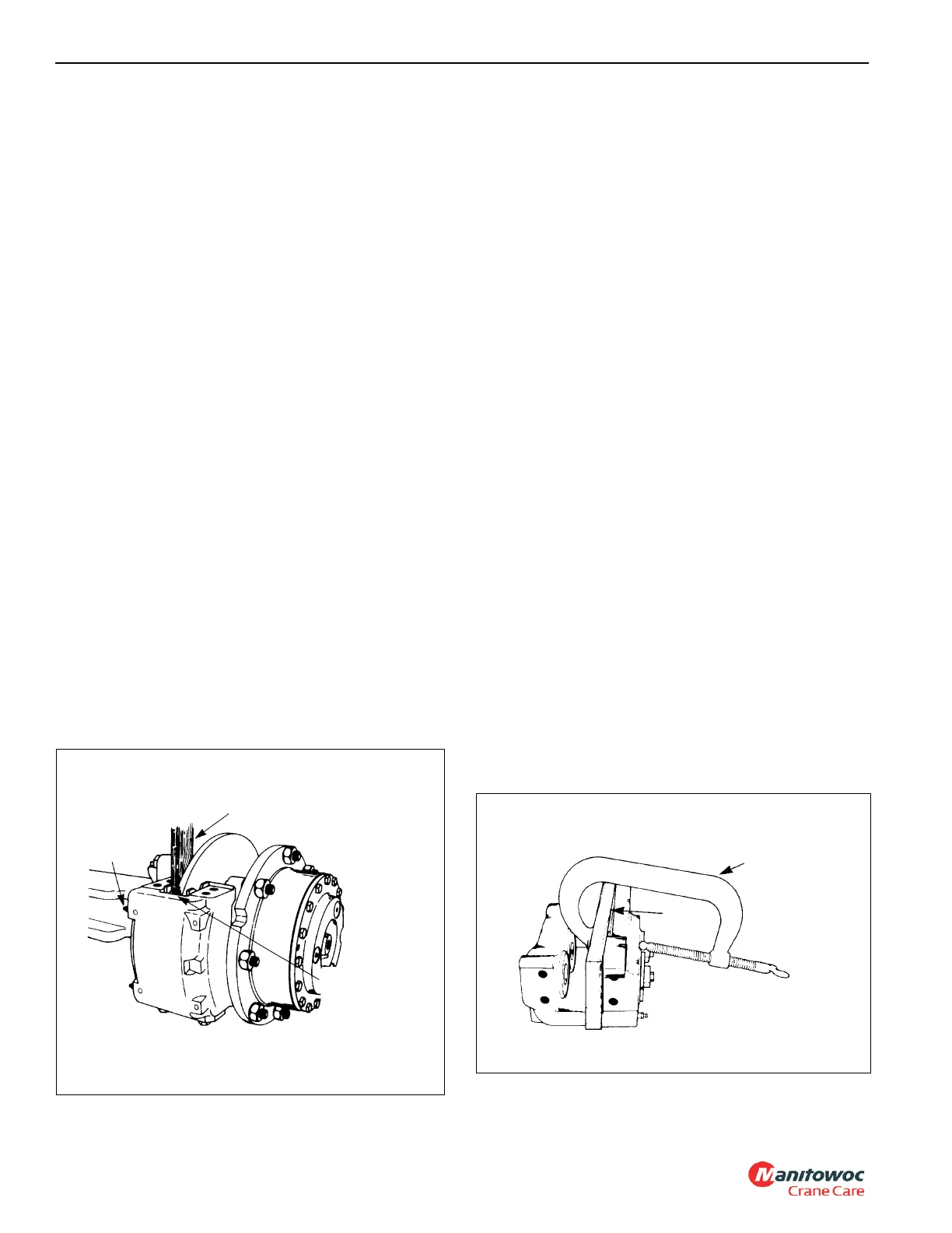
a. Use a C-clamp to hold a 0.5 in (12.7 mm) block of
wood against three pistons on the mounting side of
the housing. Ensure the C-clamp is not in the area in
front of the piston bore (Figure 8-6).
FIGURE 8-5
Wood Block
Loosen
Bleeder
Screws
Push wood
block against
linings to push
pistons into
bores
Wood
Block
C-Clamp
FIGURE 8-6

 Loading...


