Grove Published 11-22-2016, Control # 345-12 2-27
RT9130E-2 SERVICE MANUAL HYDRAULIC SYSTEM
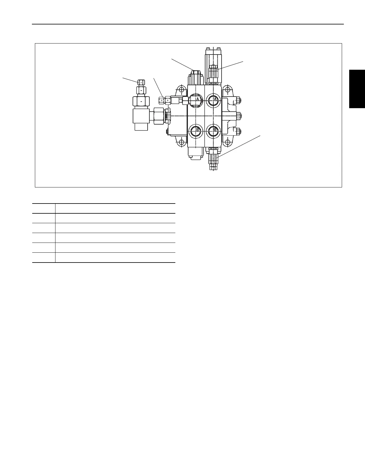
Procedure I - For Checking Swing Valve
Work Port Relief Pressure
1. Remove cap and install pressure gauge on swing valve
inlet test port (Figure 2-12).
2. With the swing house lock Engaged and the engine
running at FULL RPM, swing LEFT and adjust “A” port
swing relief to 2500 psi
±50 (17.2 MPa ±0.4).
3. With the swing house lock Engaged and the engine
running @ FULL RPM, swing RIGHT and adjust “B” port
swing relief to 2500 psi
±50 (17.2 MPa ±0.4).
4. Remove pressure gauge from the swing inlet test port
and reinstall cap.
Procedure J - For Checking Relief Setting
for Counterweight Supply Control Valve
1. Remove cap and install gauge on load sense relief test
port on main directional control valve (Figure 2-7).
2. Operate the counterweight directional control valve by
fully raising or lowering the counterweight cylinders.
Adjust the counterweight removal directional control
valve load sense relief valve to 3800 psi
±50 (26.2 MPa
±0.4).
3. In the cab, press the Luffing Extension Switch to ON and
the Luffing Raise/Lower Switch to LOWER in the LH
armrest. Adjust the luffing extension “B” port relief valve
to 1450 psi
±50 (10.0 MPa ±0.4) (Figure 2-13).
4. In the cab, press the cab Tilt Switch to the RAISE
position and adjust the cab tilt “A” port relief valve to
2500 psi
±50 (17.2 MPa ±0.4).
5. In the cab, press the cab Tilt Switch to the LOWER
position and adjust the cab tilt “B” port relief valve to
2500 psi
±50 (17.2 MPa ±0.4).
6. Disconnect the couplers for the counterweight pin from
the cylinder located at the rear of the turntable. DO NOT
PERFORM THIS TEST IF THE COUPLERS ARE
CONNECTED TO EITHER THE COUNTERWEIGHT
PIN CYLINDER OR THE BOOM PIVOT CYLINDER!
Operate the counterweight pin lever to retract. Adjust the
counterweight pin “B” port relief to 1600
± 50 psi (11.0 ±
0.4 MPa).
7. Operate the counterweight pin lever to extend. Adjust
the counterweight pin “A” port relief to 2500 psi
±50
(17.2 MPa
±0.4). Connect the couplers to the
counterweight pin cylinder.
FIGURE 2-12
7128-4
Swing/Steer Directional Control Valve
1
2
3
4
5
Item Description
1 Steer Priority Flow Divider Section Relief
2 Steering Load Sense Test Port
3 Swing Inlet Test Port
4 Swing Relief “A” Port
5 Swing Relief “B” Port

 Loading...


