Grove Published 11-22-2016, Control # 345-12 2-49
RT9130E-2 SERVICE MANUAL HYDRAULIC SYSTEM
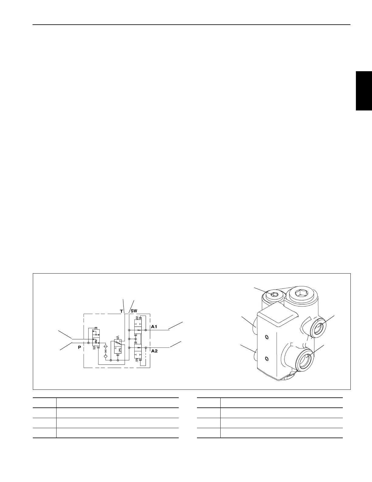
DUAL ACCUMULATOR CHARGE VALVE
Description
The dual accumulator charge valve Figure 2-29 is located on
the turntable left side, inside the superstructure. The purpose
of the valve is to provide a priority regulated flow dependent
on the maximum pressure required to the service brake
circuit and a secondary source of flow for the front steer and
swing circuits. The dual accumulator charge valve regulates
flow to the hydraulic accumulators at a rate of 2.2 to 3.2 gpm
(8.3 to 12.1 l/min) to provide stored energy for the primary
(front) and the secondary (rear) service brake circuits.
The dual accumulator charge valve consists of a charging
section with a proportional flow divided spool and a main
check valve, a control section with a pilot spool with a low
limit check ball and a high limit check ball, and an inverted
shuttle cartridge.
When the valve is charging the accumulators, the
proportional flow divider spool, in the charging section, is in
neutral to allow the charging flow to pass through the main
check valve and on to the pilot control section and the
inverted shuttle cartridge. The pilot control section controls
the opening and closing of the low and high limit check balls.
The pilot spool permits only one of these balls to be open at
any one time. When the low limit check ball is open, the
pressure from the accumulators is applied to shift the
charging section flow divider spool and allow pump flow to
the inverted shuttle cartridge which is normally open to
charge the accumulators.
When the accumulators are charged to the high limit
pressure of 2750 psi (19,000 kPa), pilot pressure will open
the high limit check ball and close the low limit check ball.
The inverted shuttle senses the pressure in the
accumulators and the brake circuits to pilot close the
cartridge when the maximum pressure is reached. After the
accumulators are fully charged, the high limit check ball
opens and the proportional flow divider spool is fully opened
to direct all of the pump flow to the excess flow port and on to
the air conditioning circuits.
Maintenance
Removal
1. Tag and disconnect the hydraulic hoses from the valve.
Cap or plug the lines and ports.
2. Remove the capscrews, flatwashers and lockwashers
securing the valve to the turntable. Remove the valve.
Installation
1. Position the valve on the turntable and secure with the
capscrews, washers and lockwashers.
2. Connect the hydraulic hoses to the valve ports as tagged
during removal.
3. Start the engine and check for leaks. Make repairs as
needed.
4. Depress the brake pedal several times, make several
turns with the steering wheel, and swing the
superstructure left and right. Verify the brakes, swing,
and front steering work properly.
FIGURE 2-29
6436
1
1
2
2
3
3
4
4
5
5, 6
6
Item Description
1 Pressure port
2Switch Port
3Flow Thru Port
Item Description
4 Tank Port
5 Port A1 - To Accumulator
6 Port A2 - To Accumulator

 Loading...


