HOIST AND COUNTERWEIGHT RT9130E-2 SERVICE MANUAL
5-18 Published 11-22-2016, Control # 345-12
HOIST DRUM ROTATION INDICATOR
SYSTEM
Description
The hoist drum rotation indicator system is an electrically
operated system that provides the operator with a touch
indication of drum rotation so he will know if and at what
speed the hoist drum is rotating, even under the most
distracting conditions.
The rotation indicator system consists of two separate
electrical components; the rotation indicator sensor and
thumb thumper solenoid. The rotation sensor is located on
the hoist. The pulsing thumb thumper solenoid is located in
the applicable hoist control lever handle.
Maintenance
General
Proper circuit operation can be checked for each individual
electrical component. If a malfunction occurs within the
system, repairs should be limited to finding and replacing the
faulty component(s). If difficulty persists, contact your local
distributor for additional troubleshooting aid.
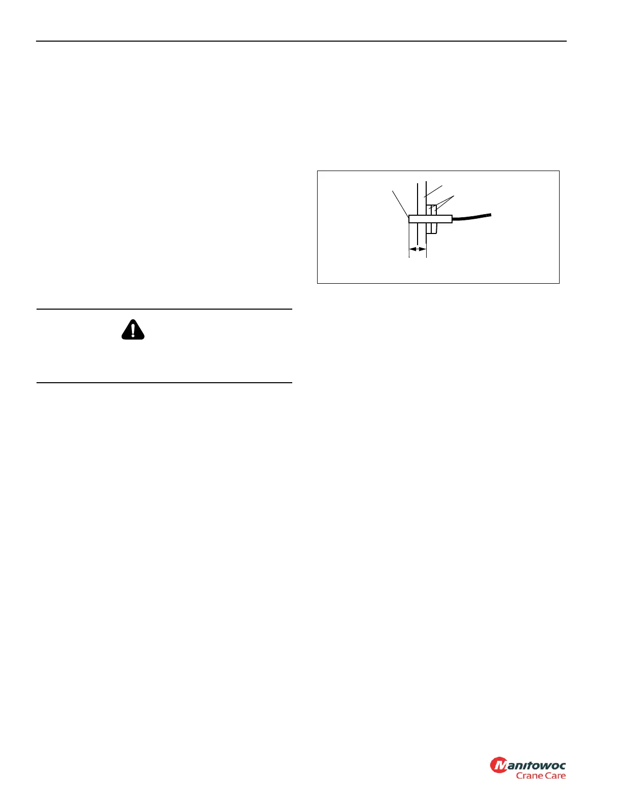
Rotation Sensor
The rotation sensor is screwed into the hoist support end
bracket that holds the hydraulic motor (Figure 5-6). It senses
the rotation of the drum. When installing the sensor, ensure
its sensing end is 1.21 in (31 mm) from the first lock nut. (This
is the length of the sensor from its sensing end through to the
outside surface of the hoist support end bracket.) If sensor
will not work properly, loosen both lock nuts and turn the
sensor counterclockwise up to one turn, then re-tighten lock
nuts to hold sensor position. If sensor will still not work
properly, ensure its sensing end is 1.21 in (31 mm) from the
first lock nut, then turn the sensor clockwise up to one turn,
then re-tighten lock nuts to hold sensor position.
Thumb Thumper Solenoid
The thumb thumper solenoid provides feedback proportional
to the hoist line speed by pulsing the rubber button on top of
the hoist control lever.
Troubleshooting
Using a digital VOM check if the thumper solenoid resistance
is 6-10 ohms. If it doesn’t measure correctly the solenoid is
worn or damaged and should be replaced.
Using a digital VOM, measure the voltage in the thumper
solenoid between wires 508 and 51, for the main hoist, or
509 and 51, for the auxiliary hoist. The voltage should
measure 12v ± 10 percent, if it doesn’t, check the voltage on
the superstructure module pin A01, for the main hoist, and
pin A02, for the auxiliary hoist. If voltage is within range but
not present at the solenoids, the power or ground wires are
defective, replace wires as necessary.
CAUTION
Disconnect the batteries before performing any
maintenance on this system. Serious burns may result
from accidental shorting or grounding of live circuits.
Support End Bracket
1.21 in. (31 mm)
Lock Nuts
Sensing End
FIGURE 5-6
7068

 Loading...


