Grove Published 11-22-2016, Control # 345-12 4-5
RT9130E-2 SERVICE MANUAL BOOM
lengths behave in accordance with customary practice, in
that they reduce to the figure applicable to that adjacent
boom length having lower capacities (either the next longer
or shorter rated boom length, according to the particular load
chart in use), whenever the actual boom length differs from
the rated length by more than 500 mm. (For any given boom
length, the capacities vary steplessly with load radius
according to the particular calibration curves).
Hydraulic Actuation and Control System
Extension of the inner mid, center mid, and outer mid
sections occurs by way of three hydraulic cylinders (one 2-
stage cylinder moving the inner mid and center mid sections,
and one single-stage cylinder, moving the outer mid section).
The fly section is cable extended and retracted by the
movement of the outer mid section and center mid sections,
and thus is mechanically synchronized with the outer mid
section, but the other sections are electro-hydraulically
sequenced/synchronized by the boom telescoping control
system.
Controlling the telescope cylinders, the boom telescoping
hydraulic actuating system consists of the following
elements:
a. A single pilot pressure joystick or foot pedal
controller, which actuates two pilot operated 4-way,
3-position, pressure compensated proportional
control valves controlling the flow and pressure of
hydraulic oil respectively to the inner mid and center
mid/outer mid section telescope circuits.
b. The propositional control valve(s) noted in a. above,
in which are incorporated solenoid operated
proportional pressure reducing valves in both of the
valves’ pilot pressure spool actuator sections (i.e.
both “extend” and “retract” directions), acting to vary
the pilot pressure being applied to shift the valve
spool, and thereby controlling the flow of oil to the
inner mid center mid, outer mid section telescope
cylinders. Thus, when so directed by electrical
signal, the pressure reducing valves effectively
override the pilot pressure signal being transmitted
from the operator’s pilot controller to the telescope
control valves, automatically opening, feathering
and closing so as to initiate, control and halt motion
of the respective sections according to the
predetermined sequence.
c. Mechanically actuated valves sensing the status of
the center mid and outer mid sections (i.e. outer mid
section fully retracted, and center mid section fully
extended) and diverting the flow of oil, when
extending, from the center mid section cylinder to
the outer mid cylinder when the center mid section
(and therefore also the inner mid section) is fully
extended, and vice versa during boom retraction.
Thus the outer mid section is not able to receive any
oil to extend until the center mid section is already
fully extended; and similarly, no “retract” oil will flow
to the center mid section until the outer mid section
is fully retracted.
d. A normally closed, solenoid operated 2-way, 2-
position control valve, which bleeds off residual rod
side pressure from the telescope cylinders (as
selected by a double check valve, according to the
cylinder being telescoped, and an orifice to prevent
significant loss of oil to tank that would compromise
cylinder retraction speed). The purpose of this valve
is to allow residual pressure trapped in the rod side
of the cylinders to escape, preventing subsequent
unseating of the holding valve and transfer of the
trapped oil to the piston side, which can cause a
slight spontaneous and unwanted extension of the
boom sections
e. Unless overridden by the pilot signal pressure
reducing valves in paragraph b. (above), the oil flow
and pressure applied to the telescoping cylinders is
under the direct control of the joystick pilot
controller.
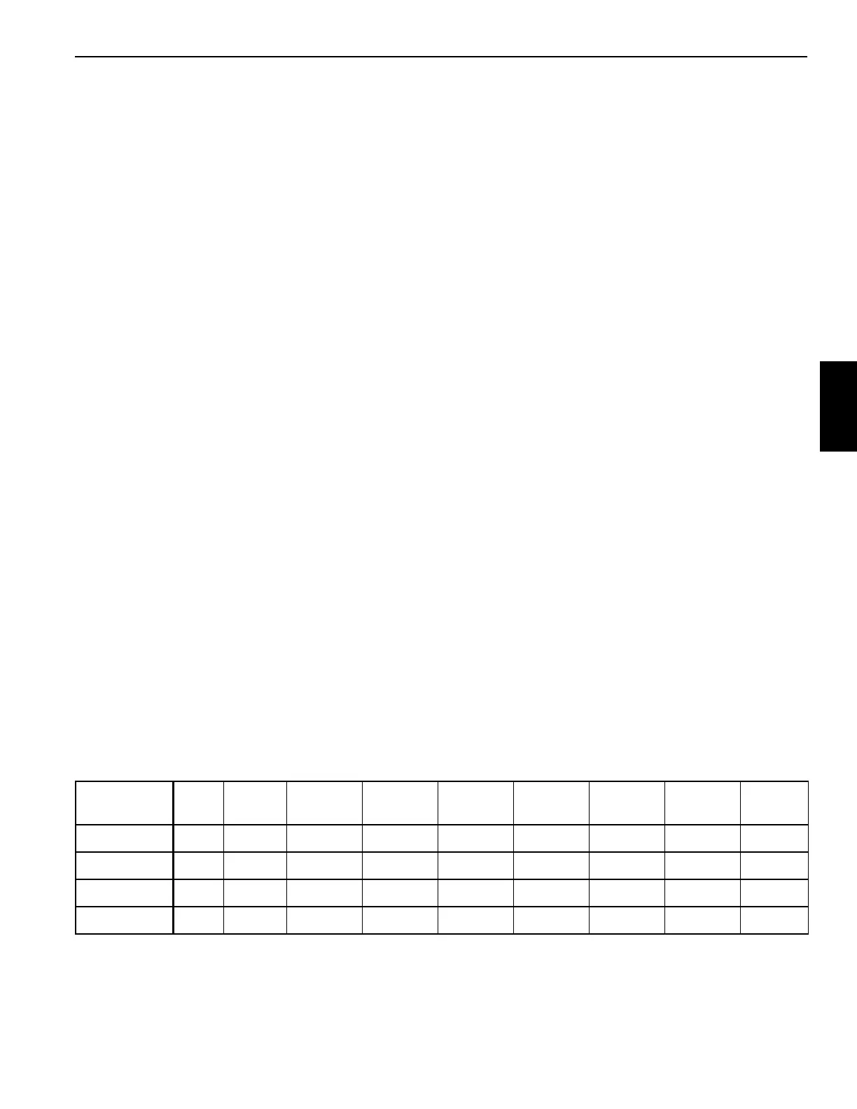
Table 4-1: Boom Section Extension Proportions
Boom
Length (ft)
42 56.68 71.34 86 100.67 115.34 130 144.67 159.33
Inner-Mid 0 50 75 75 100 100 100 100 100
Center-Mid 0 0 25 75 100 100 100 100 100
Outer-Mid 000 0 0 255075100
Fly 000 0 0 255075100

 Loading...


