HOIST AND COUNTERWEIGHT RT9130E-2 SERVICE MANUAL
5-24 Published 11-22-2016, Control # 345-12
1. Position the crane on a firm level surface.
2. Fully extend and set the outriggers. Level the crane.
3. Position the superstructure over the rear with the
counterweight positioned over the counterweight
support on the front of the carrier frame.
4. Remove any load handling device from the auxiliary
hoist cable and retract all cable onto the hoist drum.
Secure the cable.
5. Tag and disconnect the auxiliary hoist hydraulic lines
and electrical harnesses. Cap or plug all line openings.
Secure lines so they will not be damaged during
auxiliary hoist structure removal.
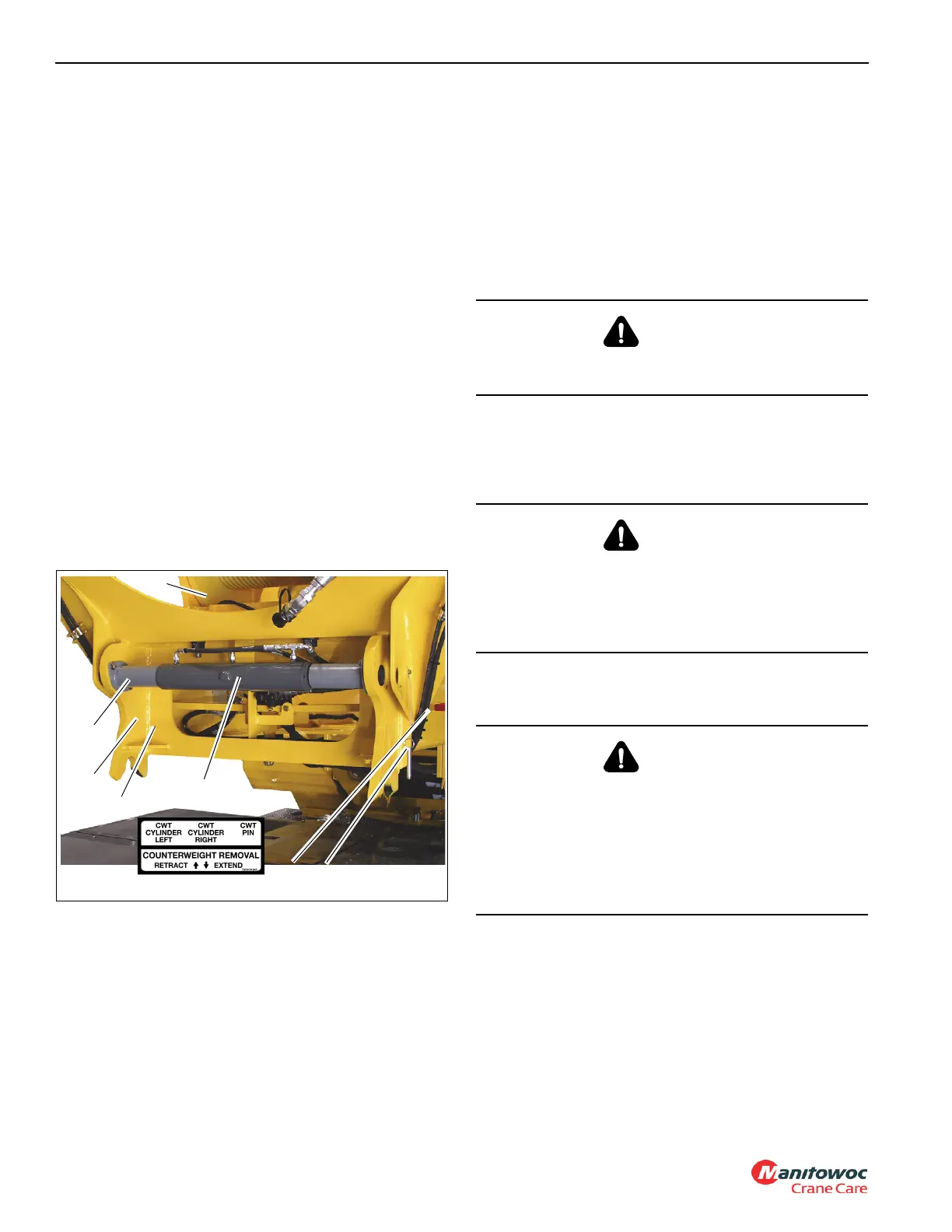
6. Do not disconnect the lines to the counterweight
removal cylinders (5) (Figure 5-13) at this time.
NOTE: It may be necessary to retract the counterweight
removal cylinders (5) (Figure 5-13) to relieve
weight from the counterweight to auxiliary hoist
structure pins (12) (Figure 5-13).
7. Remove the hitch pins (11) (Figure 5-13) and the
counterweight to hoist structure pins (12) (Figure 5-13).
These are accessible through the holes in the back of
the counterweight (1) (Figure 5-13).
8. Using the counterweight removal levers (6)
(Figure 5-14), extend the counterweight removal
cylinders (5) (Figure 5-13) and carefully lower the
counterweight (1) (Figure 5-13) onto the counterweight
supports.
9. Remove the detent pins (4) (Figure 5-14) to allow the pin
removal cylinder (2) (Figure 5-14) to retract the pins on
its rod ends.
10. Use the counterweight removal levers (6) (Figure 5-14)
to retract the pins on the rod ends of the pin removal
cylinder (2) (Figure 5-14) and unpin the auxiliary hoist
structure (7) (Figure 5-14) from the turntable.
11. Retract the counterweight removal cylinders (5)
(Figure 5-13) and carefully lower the auxiliary hoist
structure (7) (Figure 5-14) onto the counterweight.
12. Tag, disconnect and secure the counterweight removal
cylinder hydraulic lines. Cap or plug all line openings.
13. Secure the counterweight (1) (Figure 5-13) to the
auxiliary hoist structure (7) (Figure 5-14) with the
counterweight to hoist structure pins (12) (Figure 5-13)
and hitch pins (11) (Figure 5-13).
14. Disengage the swing lock pin and swing the
superstructure over the front.
15. Attach an adequate lifting device with slings to the
auxiliary hoist structure (7) (Figure 5-14). Use the crane
to carefully transfer the auxiliary hoist structure (7)
(Figure 5-14) and counterweight (1) (Figure 5-13) to the
ground or suitable transport vehicle.
NOTE: Step 16 applies to the heavy removable
counterweight (2) (Figure 5-13).
WARNING
Travel is not permitted with any counterweight on the
carrier.
WARNING
Do not attempt to separate the auxiliary hoist structure (7)
(Figure 5-14) from the counterweight (1) (Figure 5-13)
while on the counterweight stand (1) (Figure 5-12). The
auxiliary hoist structure (7) (Figure 5-14) may hit the
counterweight (1) (Figure 5-13) and knock it off the stand.
WARNING
Death or serious injury may result with improper use!
On the heavy removable counterweight option (2)
(Figure 5-13), do not use the lifting lugs on the heavy
counterweights to lift the entire heavy counterweight and
auxiliary hoist structure. The heavy counterweight lifting
lugs are designed to lift the heavy removable
counterweight only.

 Loading...


