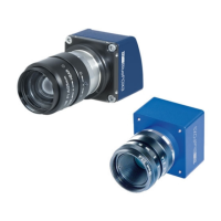
Figure 12: mvBlueFOX3-M2xxx-1xx2 dimensions and connectors
8.2 Camera interfaces
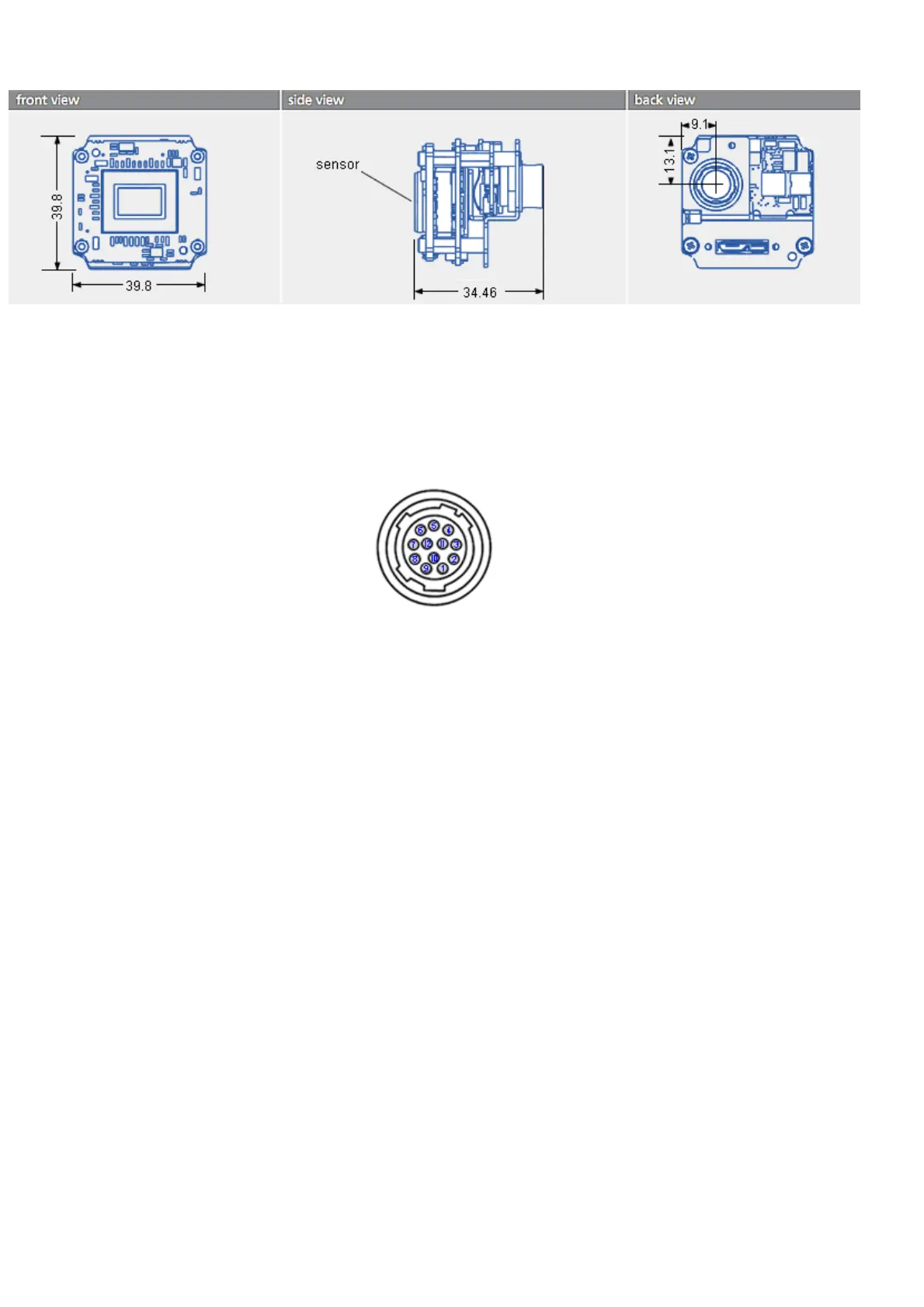
8.2.1 Circular connector male (Power / Digital I/O)
Figure 13: Hirose 12-pin (male; top view), digital I/O, power
Pin.
mvBlueFOX3-1xxx |
Signal
mvBlueFOX3-2xxx |
Signal
Line in
wxPropView
Cable KS-BCX-HR12
color scheme
1 GND (for VDC) black
2
not connected, leave
open
12V - 24V brown
3 Opto DigOut3 Line3 red
4 Opto DigIn0 Line4 orange
5 Opto DigOut2 Line2 yellow
6 Opto DigOut0 Line0 green
7 IN_COMMON (DigIn GND) blue
8 RS232 RX violet
9 RS232 TX gray
10 OUT_V+ white
11 Opto DigIn1 Line5 white-black
12 Opto DigOut1 Line1 white-brown
Main connector shield
Main connector
shield
Main shield
8 Technical data
56
 Loading...