TIMING, SYNCHRONIZING & ADJUSTING
Page 2C-6 90-855347R1 JANUARY 1999
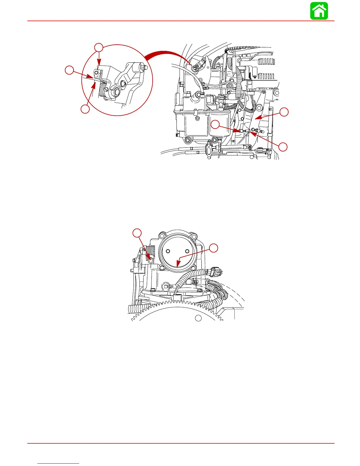
4. Check for free play (roller lifts from cam) between roller and cam at full throttle to pre-
vent linkage from binding. Readjust full throttle stop screw, if necessary
.
a
b
c
56062
d
e
f
a
b
c
d
e
f
a-Throttle Arm
b-Stop
c-Full Throttle Stop
Screw
d-Throttle Shaft Arm
e-0.020 in. (0.508 mm) Clearance
f-Stop on Attenuator Box
Throttle Plate Screw
IMPORTANT: DO NOT adjust throttle plate stop screw from factory setting. Howev-
er, should the throttle plate require adjustment, use the throttle plate stop screw
to set the throttle plate clearance @ 0.045 in. (1.143 mm) using a #56 drill.
a
56151
b
a
b
a-Throttle Plate Stop Screw
b-Throttle Plate Clearance – Set @ 0.045 in. (1.143mm)
Throttle Position Sensor (TPS) Adjustment
The Throttle Position Sensors are not adjustable. TPS settings can be monitored with the
Digital Diagnostic Terminal through the ECM. If TPS settings are not within specifications,
refer to Section 2A.
Idle Speed
Engine idle speed is not adjustable. The parameters affecting idle speed can be checked
and monitored by the DDT. Refer to the DDT Reference Manual for complete details.
 Loading...


