2
A
IGNITION
90-855347R1 JANUARY 1999 Page 2A-1
ELECTRICAL
Section 2A – Ignition
Table of Contents
Specifications 2A-1. . . . . . . . . . . . . . . . . . . . . . . . . . . . . . . .
Special Tools 2A-2. . . . . . . . . . . . . . . . . . . . . . . . . . . . . . . .
Electrical Components 2A-4. . . . . . . . . . . . . . . . . . . . . . . .
Theory of Operation 2A-6. . . . . . . . . . . . . . . . . . . . . . . . . .
Ignition Component Description 2A-6. . . . . . . . . . . . . . . .
Electronic Control Module (ECM) 2A-6. . . . . . . . . . . .
Flywheel 2A-7. . . . . . . . . . . . . . . . . . . . . . . . . . . . . . . . .
Ignition Coils 2A-7. . . . . . . . . . . . . . . . . . . . . . . . . . . . . .
Crank Position Sensor 2A-7. . . . . . . . . . . . . . . . . . . . .
Throttle Position Sensor (TPS) 2A-7. . . . . . . . . . . . . .
Charging System Alternator 2A-7. . . . . . . . . . . . . . . . .
Temperature Sensor 2A-8. . . . . . . . . . . . . . . . . . . . . . .
Manifold Absolute Pressure (MAP) Sensor 2A-9. . .
Air Temperature Sensor 2A-9. . . . . . . . . . . . . . . . . . . .
Direct Injectors 2A-9. . . . . . . . . . . . . . . . . . . . . . . . . . . .
Fuel Injectors 2A-9. . . . . . . . . . . . . . . . . . . . . . . . . . . . .
Disconnecting Harness Connectors from
Ignition Coils and/or Injectors 2A-9. . . . . . . . . . . . . . .
Troubleshooting 2A-9. . . . . . . . . . . . . . . . . . . . . . . . . . .
Troubleshooting Without Digital Diagnostic
Terminal 2A-10. . . . . . . . . . . . . . . . . . . . . . . . . . . . . . . . . . .
Troubleshooting With the Digital Diagnostic
Terminal 2A-11. . . . . . . . . . . . . . . . . . . . . . . . . . . . . . . . . . .
Notes 2A-12. . . . . . . . . . . . . . . . . . . . . . . . . . . . . . . . . . . . . .
DDT Functions 2A-13. . . . . . . . . . . . . . . . . . . . . . . . . . . . . .
DFI Troubleshooting Guide 2A-15. . . . . . . . . . . . . . . . . . .
Ignition Components Removal and Installation 2A-18. .
Flywheel Cover Removal and Installation 2A-18. . . .
Electronic Control Module (ECM) 2A-19. . . . . . . . . . .
Ignition Module (Coil) 2A-20. . . . . . . . . . . . . . . . . . . . .
Crank Position Sensor 2A-21. . . . . . . . . . . . . . . . . . . .
Throttle Position Sensors (TPS) 2A-21. . . . . . . . . . . .
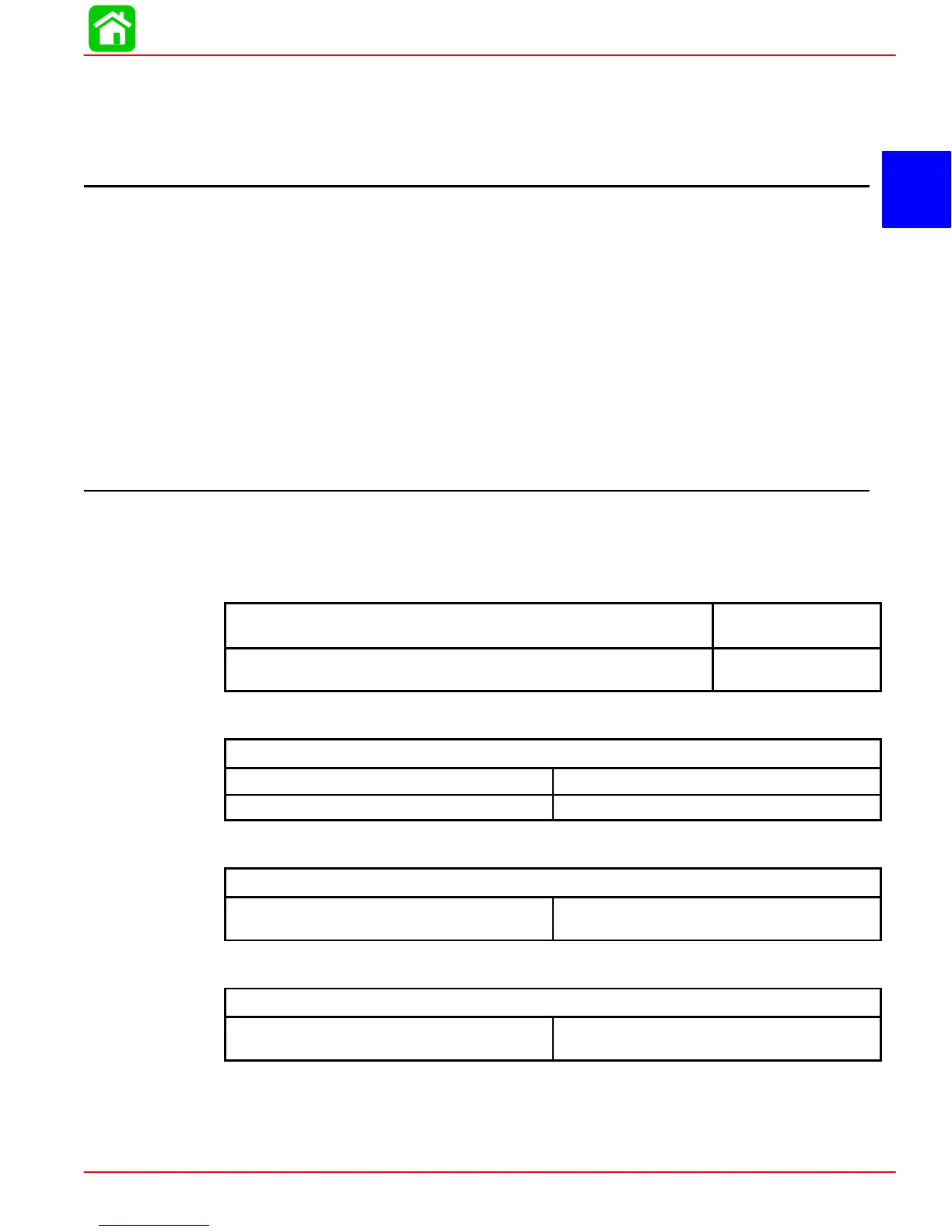
Specifications
Ignition Coil Ohm Test
Connect meter leads between primary terminal (GRN/Striped)
and ground (BLACK) terminal pin.
0.38 - 0.78
Connect meter leads between spark plug wire/high voltage
tower and ground terminal pin.
8.1 - 8.9 k
Temperature Sensor Test (Refer to Chart page 2A-8)
Temperature Sensor(s)
Between Black and each TAN/BLK wire. No Continuity
Between each lead and ground No Continuity
Direct Injector Test
Direct Injector Ohm Test (Injector Lead Disconnected)
Connect meter leads between each in-
jector terminal pin.
1 - 1.6
Fuel Injector Test
Fuel Injector Ohm Test (Injector Lead Disconnected)
Connect meter leads between each in-
jector terminal pin.
1.7 - 1.9
 Loading...


