CHARGING & STARTING SYSTEM
Page 2B-16 90-855347R1 JANUARY 1999
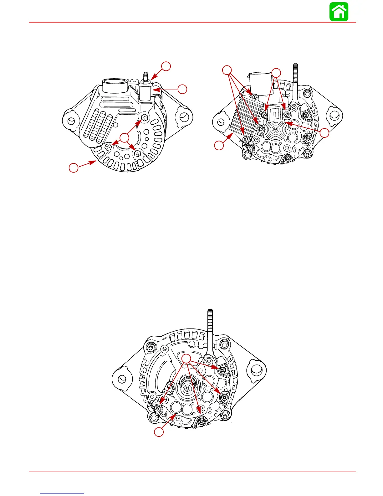
Disassembly and Test
1. Remove 3 screws and nut securing end cover and remove insulator and cover.
2. Remove 5 screws securing regulator and brush assembly.
51680
a
b
e
f
g
g
51683
c
d
a
b
a
b
c
d
a-Cover
b-Screws
c-Nut
d-Insulator
e-Regulator
f-Brush Assembly
g-Screws
NOTE: Proper regulator operation can be determined by VOLTAGE OUTPUT and CUR-
RENT OUTPUT, previous. If regulator does not meet specifications, replace regulator.
Torque regulator screws to 17 lb-in (2 Nm).
NOTE: Brushes are replaced as an assembly. Inspect assembly for stuck brushes or ex-
cessive brush wear. Normal exposed brush length is 0.156 in. (4.0 mm). Minimum ex-
posed brush length is 0.059 in. (1.5 mm).
3. Remove 4 screws securing rectifier (diode assembly) to alternator.
51684
b
a
b
a-Screws
b-Rectifier (Diode Assembly)
 Loading...


