EasyManuals Logo
Home>Mercury>Outboard Motor>Optimax 175

Mercury Optimax 175 User Manual

Mercury Optimax 175
522 pages
To Next Page IconTo Next Page
To Previous Page IconTo Previous Page
Page #354 background imageLoading...
Page #354 background image
POWER TRIM
90-855347R1 JANUARY 1999 Page 5B-49
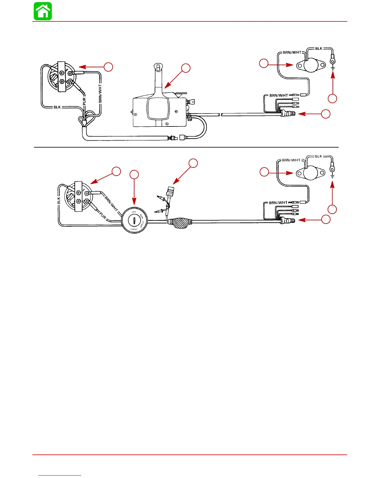
Trim Indicator Wiring Diagrams
22908
Wiring Diagram - For boats equipped with Quicksilver
Commander Series side mount remote control.
Wiring Diagram - For boats equipped with Quicksilver
Ignition/Choke and Main Harness Assembly.
a
b
c
e
d
a
f
g
c
e
d
a-Trim Indicator
b-Remote Control
c-Trim Sender
d-Engine Ground
e-To Engine
f-Ignition Switch
g-Power Trim Harness

Table of Contents

Questions and Answers:

Question and Answer IconNeed help?

Do you have a question about the Mercury Optimax 175 and is the answer not in the manual?

Mercury Optimax 175 Specifications

General IconGeneral
BrandMercury
ModelOptimax 175
CategoryOutboard Motor
LanguageEnglish

Related product manuals