WIRING DIAGRAMS
Page 2D-10 90-855347R1 JANUARY 1999
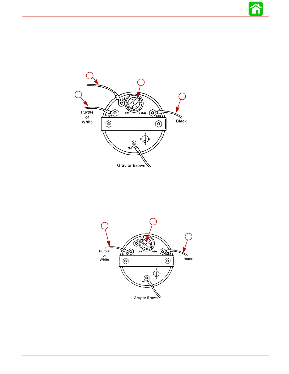
QSI Gauge Wiring Diagrams
Tachometer Wiring Diagram
Tachometer dial on back side of case must be set to position number 4.
WIRING DIAGRAM A
Use this wiring diagram when using a separate light switch for instrument lighting.
51106
a
c
d
b
a-Connect to +12 Volt
b-+12 Volt Light Switch Wire
c-Position Light Bulb to the Switched Position
d-Connect to NEGATIVE (–) Ground
WIRING DIAGRAM B
Use this wiring diagram when instrument lighting is wired directly to the ignition key switch.
(Instrument lights are on when ignition key switch is turned on.)
51106
a
b
c
a-Connect to +12 Volt
b-Position Light Bulb to the Unswitched Position
c-Connect to NEGATIVE (–) Ground
 Loading...


