POWER TRIM
Page 5B-16 90-855347R1 JANUARY 1999
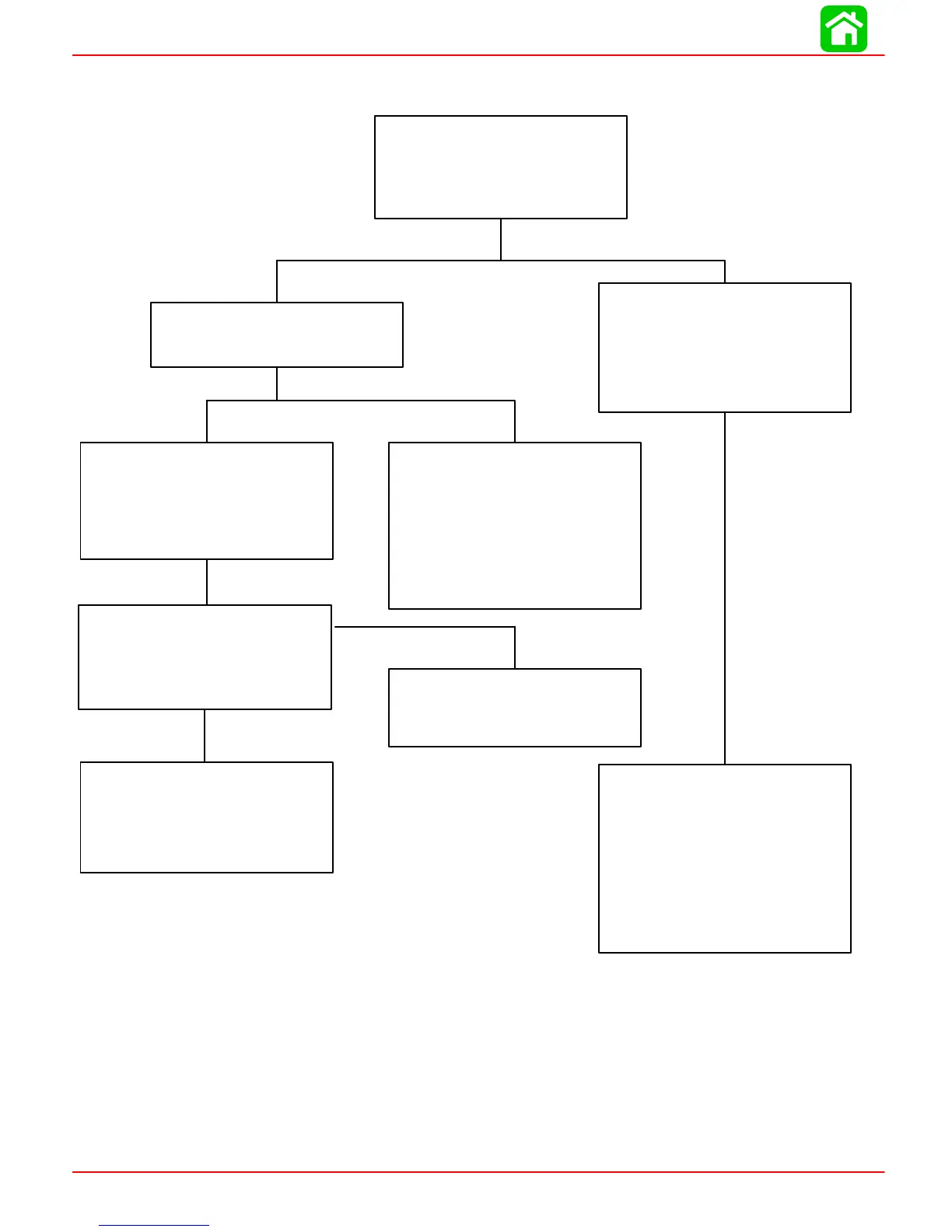
Troubleshooting the “Up” Circuit
Battery Voltage Indicated:
Battery Voltage Indicated:
No Voltage Indicated:
No Voltage Indicated:
No Voltage Indicated:
No Voltage Indicated:
Connect Voltmeter red lead to
Point 5. If battery voltage is indi-
cated, trim switch is faulty. If no
battery voltage, check for loose
or corroded connection at Point
5 or open circuit in wire supply-
ing current to Point 5.
Relay Switch is defective.
There is an open circuit be-
tween Point 9 and positive (+)
battery terminal.
•Connect Voltmeter red lead to
Point 6.
Connect Voltmeter red lead to
Point 9.
Connect Voltmeter red lead to
Point 7 and black lead to ground.
Depress “Up” trim button. If bat-
tery voltage is indicated, wire is
open between Points 7 and 8.
Connect Voltmeter red lead to
Point 8 and black lead to ground.
Depress the “Up” trim button.
•Depress “Up” trim button.
•Pump motor wiring is defec-
tive.
•Pump motor is defective.
•Check for loose or corroded
connections.
•Check wires for open.
Battery Voltage Indicated:
•Test DOWN relay.
Refer to page 5B-13 for relay
test procedure.
Relay good:
 Loading...


