WIRING DIAGRAMS
Page 2D-6 90-855347R1 JANUARY 1999
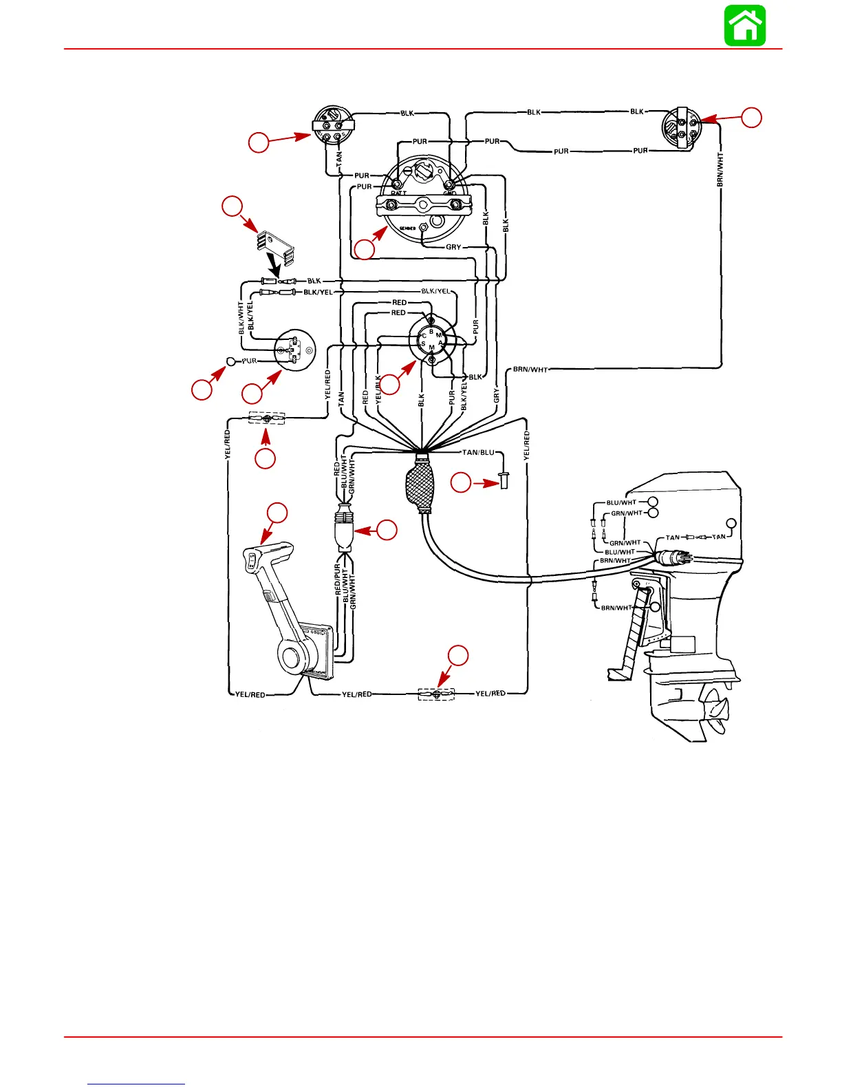
Instrument/Lanyard Stop Switch Wiring Diagram
BLK=BLACK
BLU=BLUE
BRN=BROWN
GRN=GREEN
GRY=GRAY
PUR=PURPLE
RED=RED
TAN=TAN
WHT=WHITE
YEL=YELLOW
52204
d
e
a
b
c
j
i
k
j
h
f
g
a
b
c
d
e
h
i
j
k
j
a-Ignition/Choke Switch
b-Lanyard Stop Switch
c-Lead Not Used on Outboard Installations
d-Retainer
e-Tachometer
f-Trim Indicator Gauge (Optional)
g-Temperature Gauge
h-Remote Control
i-Power Trim Harness Connector
j-Connect Wires Together w/Screw and Nut (2 Places); Apply Liquid Neoprene
to Connections and Slide Rubber Sleeve over each Connection.
k-Lead to Optional Visual Warning Kit
IMPORTANT: On installations where gauge options will not be used, tape back any
unused wiring harness leads.
 Loading...


