WIRING DIAGRAMS
90-855347R1 JANUARY 1999 Page 2D-11
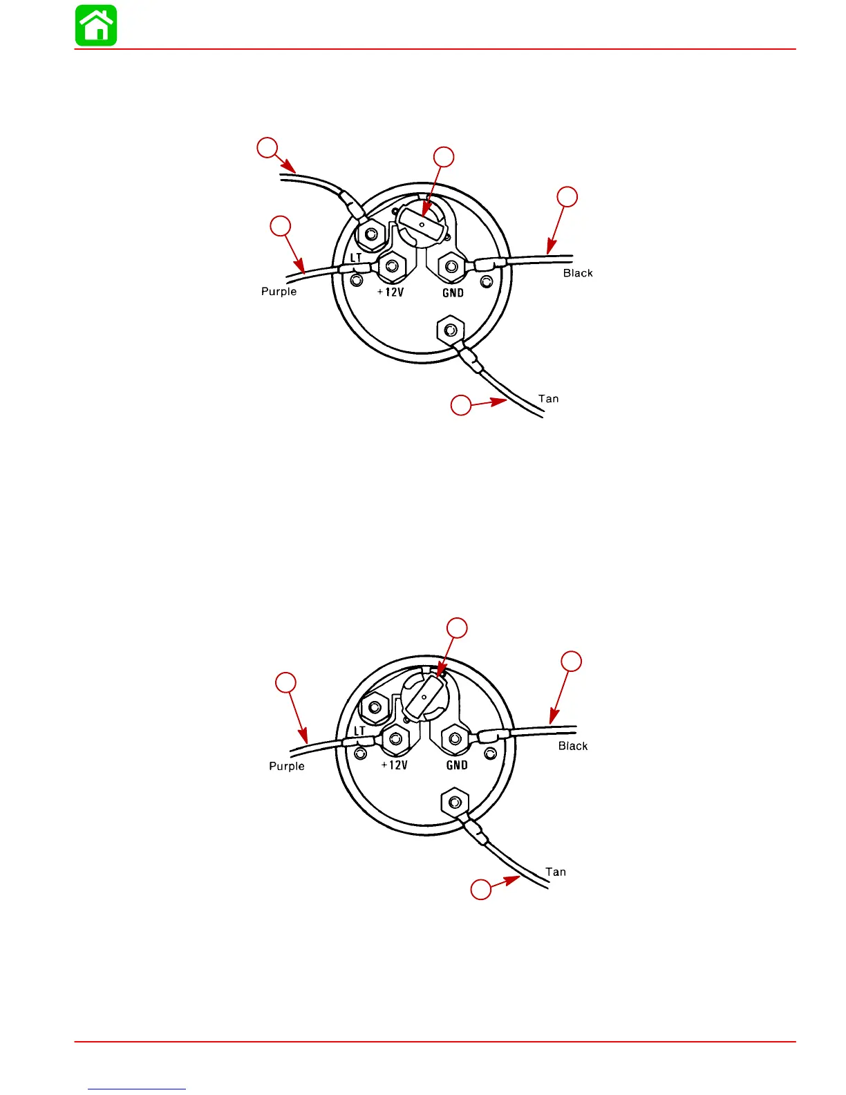
Water Temperature Gauge
WIRING DIAGRAM A
Use this wiring diagram when using a separate light switch for instrument lighting.
SEND
a
b
c
d
e
a-Connect to + 12 Volt
b-+12 Volt Light Switch Wire
c-Position Light Bulb to the Switched Position
d-Connect to NEGATIVE (–) Ground
e-Connect to TAN Lead located at the Tachometer Receptacle on Commander
Side Mount Remote Control or TAN Lead coming from Accessory Ignition/
Choke Assembly.
WIRING DIAGRAM B
Use this wiring diagram when instrument lighting is wired directly to the ignition key switch.
(Instrument lights are on when ignition key is turned on.)
51105
SEND
a
b
c
d
a-Connect to +12 Volt
b-Position Light Bulb to the Unswitched Position
c-Connect to NEGATIVE (–) Ground
d-Connect to TAN Lead located at the Tachometer Receptacle on Commander
Side Mount Remote Control or TAN Lead coming from Accessory Ignition/
Choke Assembly
 Loading...


