IGNITION
90-855347R1 JANUARY 1999 Page 2A-19
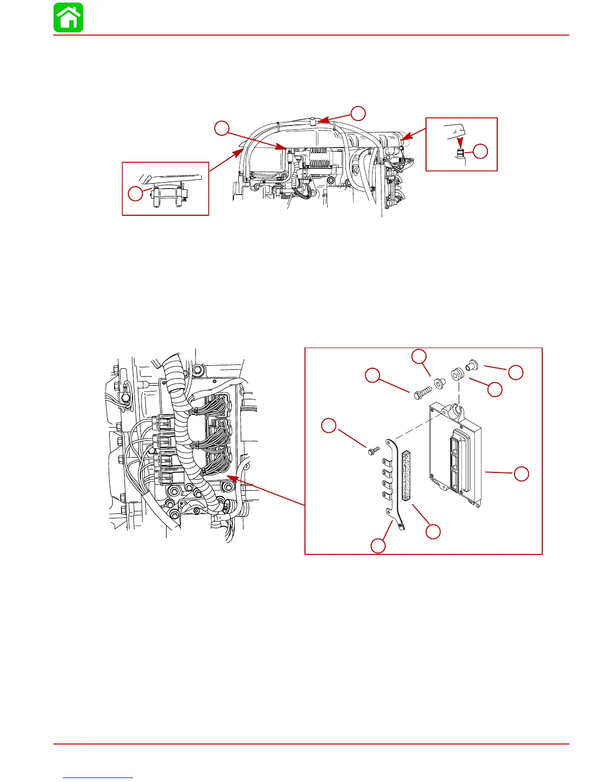
b. Push rear of the cover down onto the rear pin and air intake tube for the air com-
pressor.
c. Connect vent hose onto fitting.
d. Position hoses into holder.
a
b
d
c
a-Front Flange
b-Air Intake Tube
c-Fitting
d-Holder
Electronic Control Module (ECM)
REMOVAL
1. Disconnect ECM harness connectors.
2. Remove 3 bolts securing ECM.
a
c
b
e
f
f
g
d
a
b
c
d
e
f
f
g
a-Electronic Control Module
b-Bracket – Fuse Holder
c-Rubber Pad
d-Bolt (2) – Torque to 80 lb-in (9 N·m).
e-Bolt (3) – Torque to 80 lb-in (9 N·m)
f-Bushing
g-Rubber Grommet
INSTALLATION
1. Secure ECM to powerhead with 3 bolts.
2. Install rubber pad and bracket for the fuse holder.
3. Reconnect harness connectors.
 Loading...


