WIRING DIAGRAMS
Page 2D-14 90-855347R1 JANUARY 1999
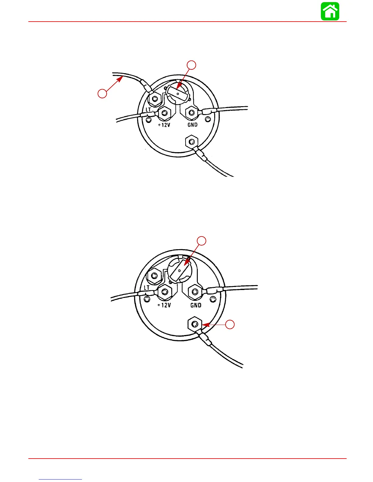
Engine Synchronizer Wiring Diagram
LIGHT BULB POSITION A
Use this position when using a separate light switch for instrument lighting.
SEND
51105
a
b
a-+12 Volt Light Switch Wire
b-Position Light Bulb to the Unswitched Position
LIGHT BULB POSITION B
Use this position when instrument lighting is wired directly to the ignition key switch. (In-
strument lights are on when ignition key switch is turned on.)
51106
a
b
a-Position Light Bulb to the Switched Position
b-Sender
Synchronizer wiring can be accomplished two different ways as an option to the user.
 Loading...


