CHARGING & STARTING SYSTEM
90-855347R1 JANUARY 1999 Page 2B-25
Troubleshooting the Starter Circuit
Before beginning the troubleshooting flow chart, verify the following conditions:
1. Confirm that battery is fully charged.
2. Check that control lever is in “NEUTRAL” position.
3. Check terminals for corrosion and loose connections.
4. Check cables and wiring for frayed and worn insulation.
5. Check 20 amp fuse.
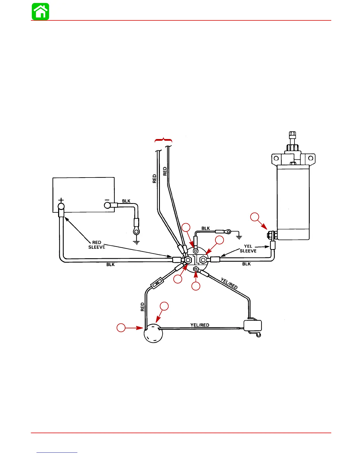
Location of “Test Points” (called out in flow chart) are numbered below.
Starter Circuit
STARTER
BATTERY
STARTER
SOLENOID
20 AMP FUSE
IGNITION SWITCH
NEUTRAL START SWITCH
(LOCATED IN CONTROL HOUSING)
TO ALTERNATOR
7
1
2
6
3
5
4
1
2
3
4
5
6
7
 Loading...


