TM-246193 Page 11
Invision 352 MPa
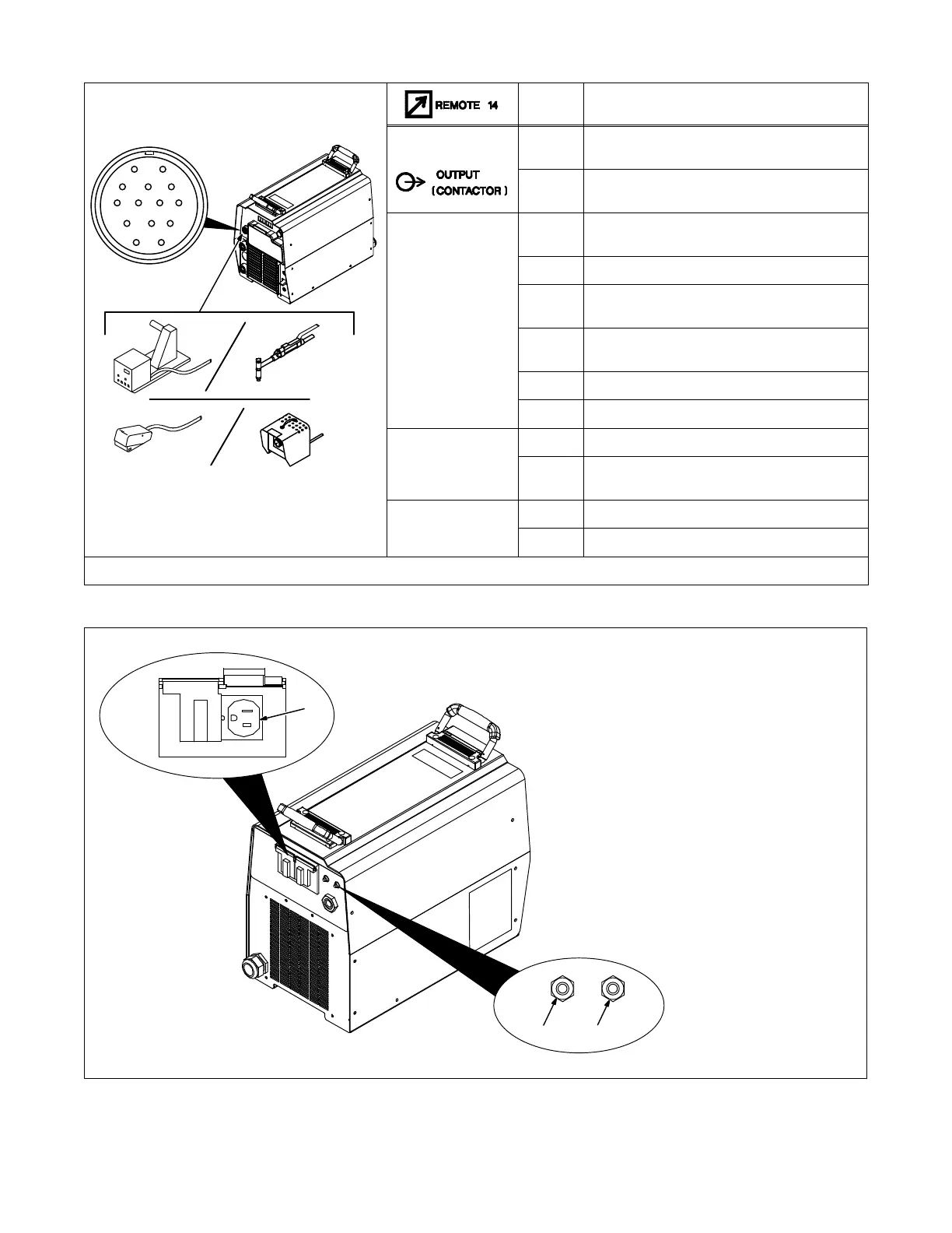
4-4. Remote 14 Receptacle Information
AJ
B
K
I
C
L
NH
D
M
G
E
F
Socket* Socket Information
24 VOLTS AC
A 24 volts AC. Protected by supplementary protect-
or CB2.
B Contact closure to A completes 24 volts AC
contactor control circuit.
REMOTE
OUTPUT
CONTROL
C Output to remote control; 0 to +10 volts DC, +10
volts DC in MIG mode.
D Remote control circuit common.
E 0 to +10 volts DC input command signal from
remote control.
L Wirefeed speed command, 0 to +10 volts DC out-
put signal from wire feeder.
M CC/CV select 0 to +10 volts DC.
N Wirefeed speed common.
A/V
AMPERAGE
VOLTAGE
F Current feedback; +1 volt DC per 100 amperes.
H Voltage feedback; +1 volt DC per 10 output recep-
tacle volts.
GND
G Circuit common for 24 volts AC circuits.
K Chassis common.
*The remaining sockets are not used.
803691-E
1 115 V 10 Amp AC Receptacle
2 Supplementary Protector CB1
3 Supplementary Protector CB2
CB1 protects duplex receptacle
from overload.
CB2 protects 24 volts AC portion of
Remote 14 receptacle from
overload.
Press button to reset supplement-
ary protector.
2 3
1
4-5. Optional 115 Volts AC Duplex Receptacle And Supplementary Protectors
 Loading...