PRE-POWER CHECKS
TM-246193 Page 35Invision 352 MPa
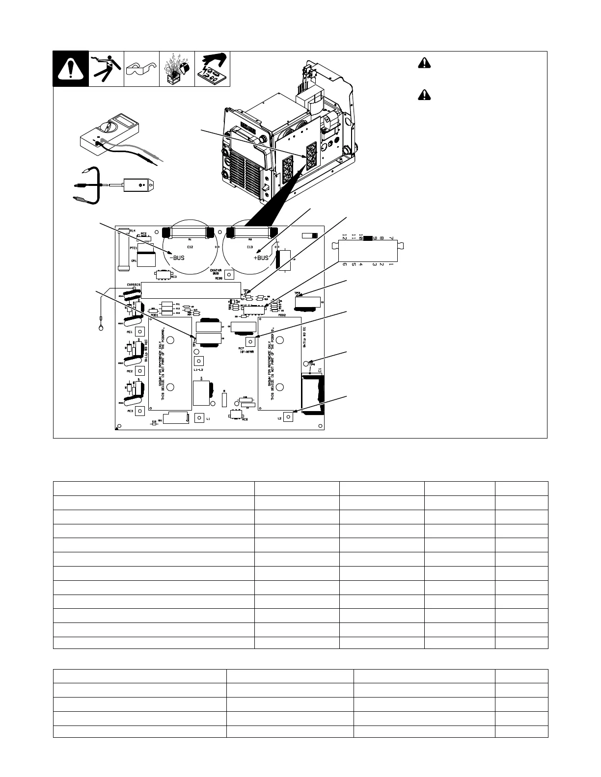
8-6. Inverter Module (MOD2)
Ref. 907161 / 258043-C
! Read and follow safety
information in Section 8-2
before proceeding.
! Wear an earth grounded
wrist strap when performing
pre-power and power off
checks. Remove wrist strap
before performing any
checks or procedures with
power applied to the ma-
chine.
Board layout may differ from
that shown.
1 MOD2
Visually inspect MOD2 for damage.
Check all measurements for MOD2
(see Section 8-7).
If any of the measurements do
not read correctly, replace
MOD2, MOD1.
NOTICE − MOD1 and MOD2 are
different and must be installed in the
proper location.
Match the number on the side of
each module to the number on PC2.
MOD1 is skiip 83 HEC
MOD2 is skiip 83 EC
The modules come as a kit with in-
stallation instructions that need to
be followed entirely.
Continue to the end of the
pre-power checks.
Test Equipment Needed:
1
Component Side Of Board
HF-XFMR
TP3
L2
+BUS
−BUS
TP1
TP4
TP2
RC1
8-7. Inverter Module (MOD2) Test Point Values
If any of the measurements do not read correctly, replace MOD2, MOD1.
Inverter Module MOD2 DMM Positive Lead DMM Negative Lead DMM Diode DMM Ohms
Boost Snubber Diode TP1 TP4 0.20 - 0.90 N/A
Boost Snubber Diode L2 TP4 0.20 - 0.90 N/A
Main Boost Diode TP4 +BUS 0.20 - 0.90 N/A
Inverter IGBT HF-XFMR +BUS 0.20 - 0.90 N/A
Inverter IGBT −BUS HF-XFMR 0.20 - 0.90 N/A
Snubber IGBT TP2 HF-XFMR 0.20 - 0.90 N/A
Snubber IGBT TP2 TP3 0.20 - 0.90 N/A
Inverter IGBT Gate (w/Plug Removed From RC1) RC1-1 HF-XFMR N/A 100k
Inverter IGBT Gate (w/Plug Removed From RC1) RC1-6 −BUS N/A 100k
Snubber IGBT Gate (w/Plug Removed From RC1) RC1-10 TP2 N/A 100k
Snubber IGBT Gate (w/Plug Removed From RC1) RC1-9 TP2 N/A 100k
Input Pre-Regulator Module MOD2 IGBT Tester Positive Lead - RED IGBT Tester Negative Lead - BLACK Gate
Inverter IGBT (w/Plug Removed From RC1) HF-XFMR −BUS RC1-6
Inverter IGBT (w/Plug Removed From RC1) +BUS HF-XFMR RC1-1
Snubber IGBT (w/Plug Removed From RC1) HF-XFMR D9 Left RC1-10
Snubber IGBT (w/Plug Removed From RC1) TP3 D9 Left RC1-9
 Loading...