PRE-POWER CHECKS
TM-246193 Page 33Invision 352 MPa
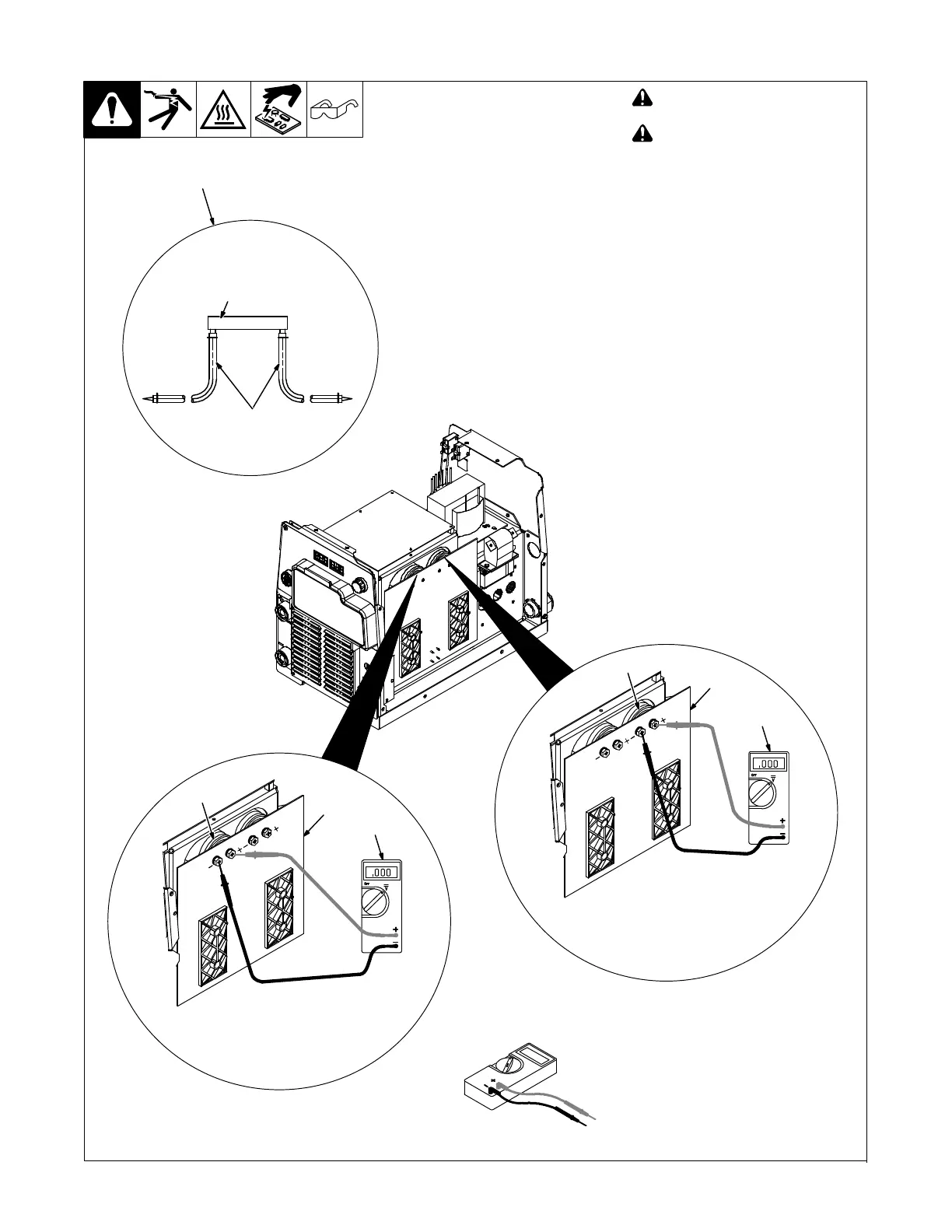
8-3. Measuring/Discharging Input Capacitor Voltage Before Working On Unit
! Turn Off welding power source,
and disconnect input power.
! Significant DC voltage can
remain on capacitors after unit is
Off. Always check the voltage as
shown to be sure the input capac-
itors have discharged before
working on unit.
Remove cover
1 Power Interconnect Board PC2
2 Voltmeter
3 Capacitor C12
Measure the DC voltage across C12
(+) Positive Terminal and C12 (−) Neg-
ative Terminal on PC2 as shown until
voltage drops to near 0 (zero) volts.
4 Capacitor C13
Measure the DC voltage across C13
(+) Positive Terminal and C13 (−) Neg-
ative Terminal on PC2 as shown until
voltage drops to near 0 (zero) volts.
If the capacitor voltage does not
drop to near zero after several min-
utes, use a bleeder resistor of be-
tween 25 and 1000 ohms, at least 5
watts, #16 AWG 1000 volts DC insu-
lating rating wire to discharge the
capacitor(s) .
5 Typical Bleeder Resistor
An example of a typical bleeder resistor
is shown on this page.
Proceed with pre-power checks.
1
2
Positive (+) lead to C12 (+) terminal,
Negative (−) lead to C12 (−) terminal
3
1
2
Positive (+) lead to C13 (+) terminal,
Negative (−) lead to C13 (−) terminal
4
Test Equipment Needed:
Typical Bleeder Resistor
25 to 1000 ohm,
5 watt resistor
#16 AWG 1000 volts DC
insulation rating, approx.
3 in. (76 mm) leads
5
Ref. 803721-B / 907161
 Loading...