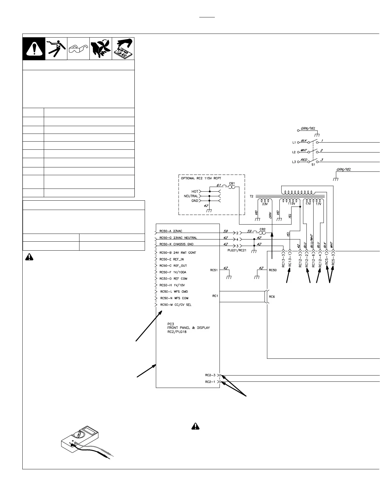
Always check unit before applying power (see Sections 8-2 thru 8-11).
TM-246193 Page 44 Invision 352 MPa
! HIGH VOLTAGE: Do not measure without
proper instrumentation.
Voltage Readings
a) Tolerance − ±10% unless specified
b) Reference − single arrow: reference to
circuit common (lead 42); double arrow:
reference to points indicated
c) Wiring Diagram − see Section 10
V1 665 volts AC RMS
V2, V3 17 volts AC RMS
V4 115 volts AC RMS
V5 24 volts AC RMS
V6, V7 470 volts DC
V8 115 volts AC RMS when FM is running
V9 +15 volts DC
V10 −15 volts DC
V11 1 volt DC per 100 amperes of weld
output
V12 72 volts DC open circuit voltage
8-18. Troubleshooting Circuit Diagram
Test Equipment Needed:
See Section 8-32 for
RC50 information
See Section 8-31 for
PC3 information
V12
V5
V4 V3 V2 V1
V1 thru V5 and V8 − use only true RMS meter
to obtain correct voltage reading.
! Measure voltage of input capacitors ac-
cording to Section 8-3, and be sure voltage
is near zero before touching any parts.
No calibration available for voltmeter V or ammeter A.
Resistance Values
a) Tolerance − ±10% unless specified
b) Turn Off unit and disconnect input power
before checking resistance
R1 thru R5 Less than 1 ohm
R6 and R7 190 − 210 ohms
Effective w/ME224001U, 115 volts
AC was removed from RC50.
 Loading...