PRE-POWER CHECKS
TM-246193 Page 37Invision 352 MPa
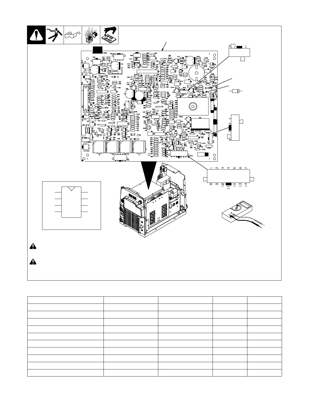
8-10. Control Board PC1
! Read and follow safety information
in Section 8-2 before proceeding.
! Wear an earth grounded wrist
strap when performing pre-power
and power off checks. Remove
wrist strap before performing any
checks or procedures with power
applied to the machine.
Remove all plugs from PC1 before
testing.
1 Control Board PC1
Visually inspect PC1 for damage.
Check all measurements for PC1.
(see Section 8-11).
If any of the measurements do not read
correctly, replace PC1.
Continue to the end of the
pre-power checks.
1
Test Equipment Needed:
1
2
3
4
8
7
6
5
Pin sequence of IC chips.
D46
KA
RC2
RC3
RC5
Ref. 276639-A / 907161
U6
8-11. Control Board PC1 − Test Point Values
Pre-Regulator Control DMM Positive Lead DMM Negative Lead DMM Diode DMM Ohms
Buck IGBT D46 Anode RC2 Pin 1 0.20 - 0.90 N/A
Buck Diode RC3 Pin 6 U6 Pin 5 0.20 - 0.90 N/A
Boost IGBT Gate Drive RC3 Pin 4 RC3 Pin 2 0.20 - 1.5 N/A
Boost IGBT Gate Drive RC3 Pin 4 RC3 Pin 3 N/A 1.9k - 2.1k
Boost IGBT Gate Drive RC3 Pin 3 RC3 Pin 4 0.20 - 0.90 N/A
60Hz Auxiliary Power Bridge DMM Positive Lead DMM Negative Lead DMM Diode DMM Ohms
Auxiliary Bridge IGBT RC5 Pin 3 RC2 Pin 1 0.20 - 0.90 N/A
Auxiliary Bridge IGBT RC5 Pin 1 RC2 Pin 1 0.20 - 0.90 N/A
Auxiliary Bridge IGBT RC3 Pin 6 RC5 Pin 3 0.20 - 0.90 N/A
Auxiliary Bridge IGBT RC3 Pin 6 RC5 Pin 1 0.20 - 0.90 N/A
 Loading...