PRE-POWER CHECKS
TM-246193 Page 36 Invision 352 MPa
! Read and follow safety information
in Section 8-2 before proceeding.
! Wear an earth grounded wrist
strap when performing pre-power
and power off checks. Remove
wrist strap before performing any
checks or procedures with power
applied to the machine.
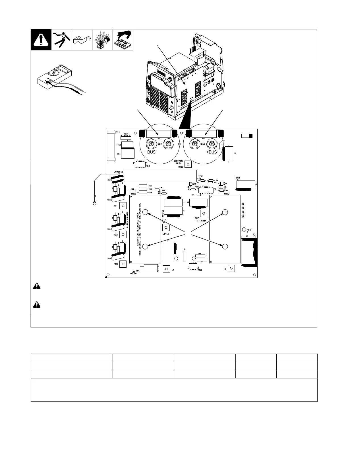
1 Power Interconnect Board PC2
2 MOD1 And MOD2 Connecting
Screws Initial Torque to (9 in. lbs (1
N
.
m) Final Torque to (20 in. lbs (2.3
N
.
m) All other connecting screws
torque to (20 in. lbs (2.3 N
.
m)
Visually inspect PC2 for damage.
Check all measurements for PC2 (see
Section 8-9).
If any measurements failed, replace
PC2 and bus capacitors.
8-8. Power Interconnect Board PC2
Ref. 907161 / 258043-C
1
Test Equipment Needed:
R8R1
2
8-9. Power Interconnect Board PC2 Test Point Values
Power Interconnect Board PC2 DMM Positive Lead DMM Negative Lead DMM Diode DMM Ohms
Bleeder Resistor R1 Center Bus −BUS N/A 37k - 41k
Bleeder Resistor R8 +BUS Center Bus N/A 37k - 41k
Because R1 and R8 are connected to capacitors C12 and C13 the resistance measurements will require several minutes to complete. A more
precise method would be to isolate R1 and R8 from the circuit. Perform this by removing the four connecting screws to C12 and C13 then slide
paper between the capacitors and PC2. If any of the measurements do not read correctly, replace PC2, capacitors C12 and C13. Continue to
the end of the pre-power checks.
 Loading...