TM-246193 Page 22
Invision 352 MPa
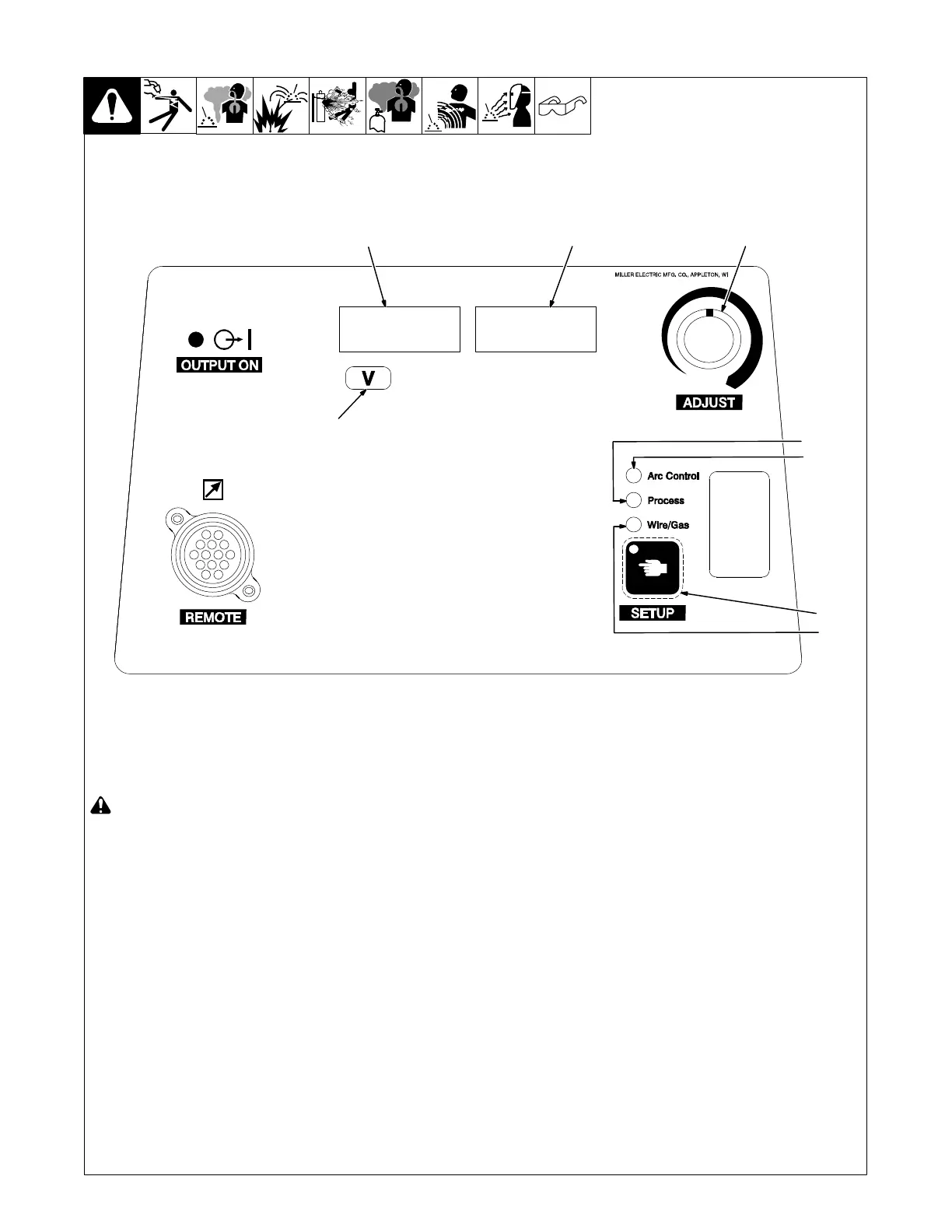
6-2. MIG Welding Mode - GMAW/FCAW Process
Ref. 235550-A
2
3
4
7
1
8
6
5
! Weld terminals are energized
through the remote control in MIG
welding mode.
1 Volts Indicator
2 Left Display
3 Right Display
4 Adjust Control
5 Process Indicator
6 Arc Control Indicator
7 Setup Button
8 Wire/Gas Indicator
Setup
For typical system connections refer to
Section 6-1.
Press Setup Button twice. The Process In-
dicator will be lit. Rotate Adjust Control to
select MIG.
Press the Setup Button again. The Wire/
Gas Indicator will be lit. The active wire type
will appear in the Left and Right Display.
Rotate Adjust Control to select desired
wire.
Press the Setup Button again. Wire/Gas In-
dicator is lit. The active gas type will appear
in the Left and Right Display.
Rotate Adjust Control to select desired gas.
Press the Setup Button to confirm the
selection. The unit will acknowledge a
change of wire and gas information by dis-
playing PROG LOAD momentarily.
For best results, select the appropriate
Wire and Gas Type to match the actual
wire and gas being used. Refer to the
MIG − Wire and Gas Selection Table
for available wires and gases (see
Section 6-3).
Operation
While the Volts Indicator is lit under the Left
Display, the Adjust Control is used to set
desired preset voltage.
The preset voltage can be adjusted re-
motely at the wire feeder if the feeder
has a voltage control. This voltage con-
trol will override the Adjust Control of
preset voltage on the welding power
source.
Pressing the Setup Button allows adjust-
ment of Arc Control, Wire Type, Gas Type
and preset voltage.
Arc Control (Inductance)
Press the Setup Button until the Arc Control
Indicator is lit. INDU appears on the Left
Display, and the corresponding inductance
setting appears on the Right Display.
Rotate Adjust Control to select desired in-
ductance setting from 0 to 100. Use lower
inductance settings to stiffen the arc and re-
duce puddle fluidity. Use higher inductance
settings to soften the arc and increase
puddle fluidity.
Refer to the MIG − Wire and Gas Selection
Table (see Section 6-3) for suggested in-
ductance setting for the specific wire and
gas being used.
Press the Setup Button to return to adjust-
ment of preset voltage.
Each Wire and Gas Type combination
has independent preset voltage and in-
ductance settings. These settings are
preserved when the unit is turned off.
5.02
 Loading...