PRE-POWER CHECKS
TM-246193 Page 39Invision 352 MPa
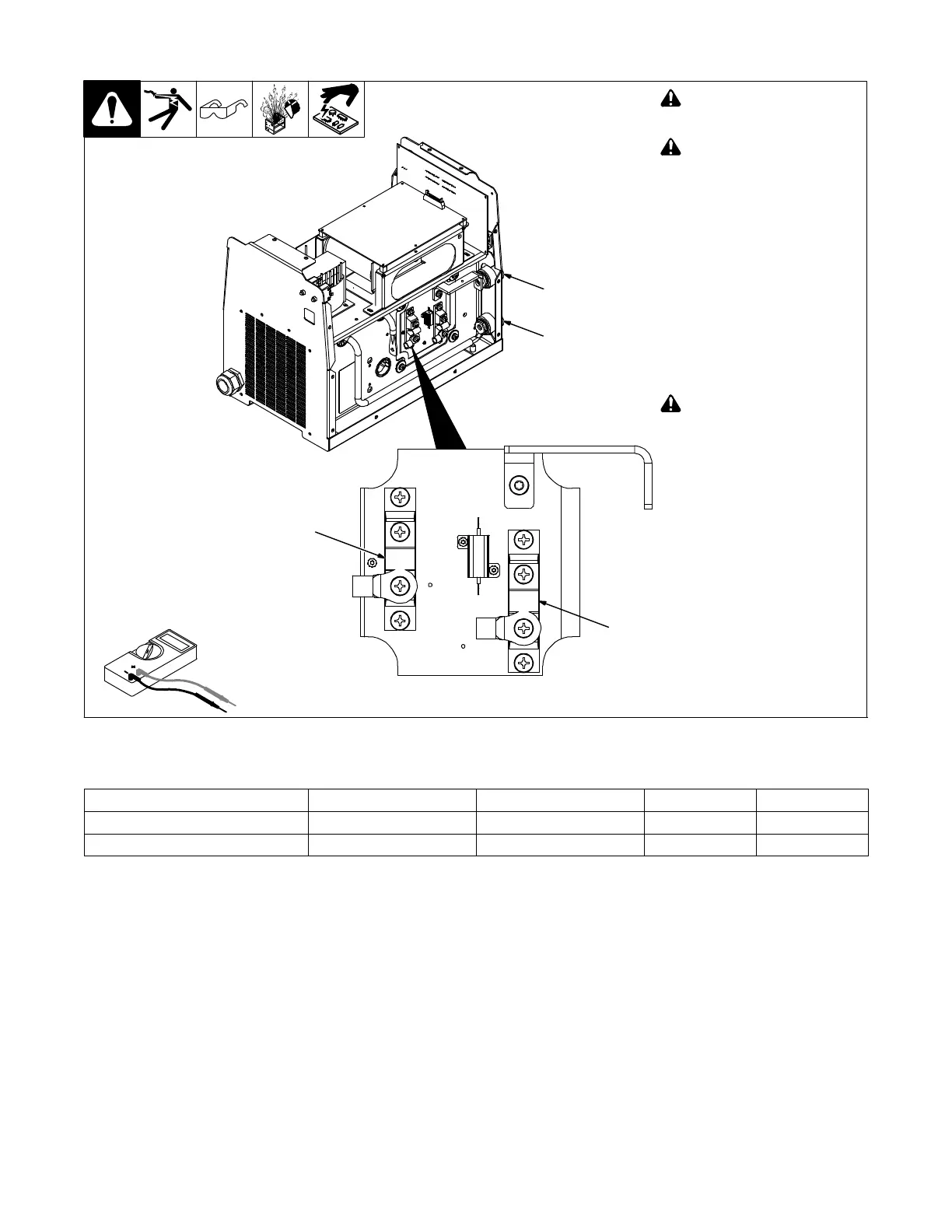
8-13. Output Diodes D1, D2
Ref. 805136-A / 805137-A
Diodes D1, D2
−
Weld Output
Receptacles
+
! Read and follow safety
information in Section 8-2
before proceeding.
! Wear an earth grounded
wrist strap when performing
pre-power checks. Remove
wrist strap before perform-
ing any checks or proce-
dures with power applied to
the machine.
1 Diode D1
2 Diode D2
Visually inspect D1 and D2 for dam-
age.
Check all measurements for output
diodes D1 and D2 (see Section
8-14).
If all measurements passed, the
output diodes D1 and D2 are OK.
! Pre-power checks are now
complete. Remove earth
grounded wrist strap before
performing any checks or
procedures with power ap-
plied to the machine.
2
1
Test Equipment Needed:
8-14. Output Diodes D1, D2 Test Point Values
Output Diodes D1 And D2 DMM Positive Lead DMM Negative Lead DMM Diode DMM Ohms
D1 Terminal Anode Secondary Heatsink 0.10 - 0.90 N/A
D2 Terminal Anode Secondary Heatsink 0.10 - 0.90 N/A
 Loading...