Always check unit before applying power (see Sections 8-2 thru 8-11).
TM-246193 Page 50 Invision 352 MPa
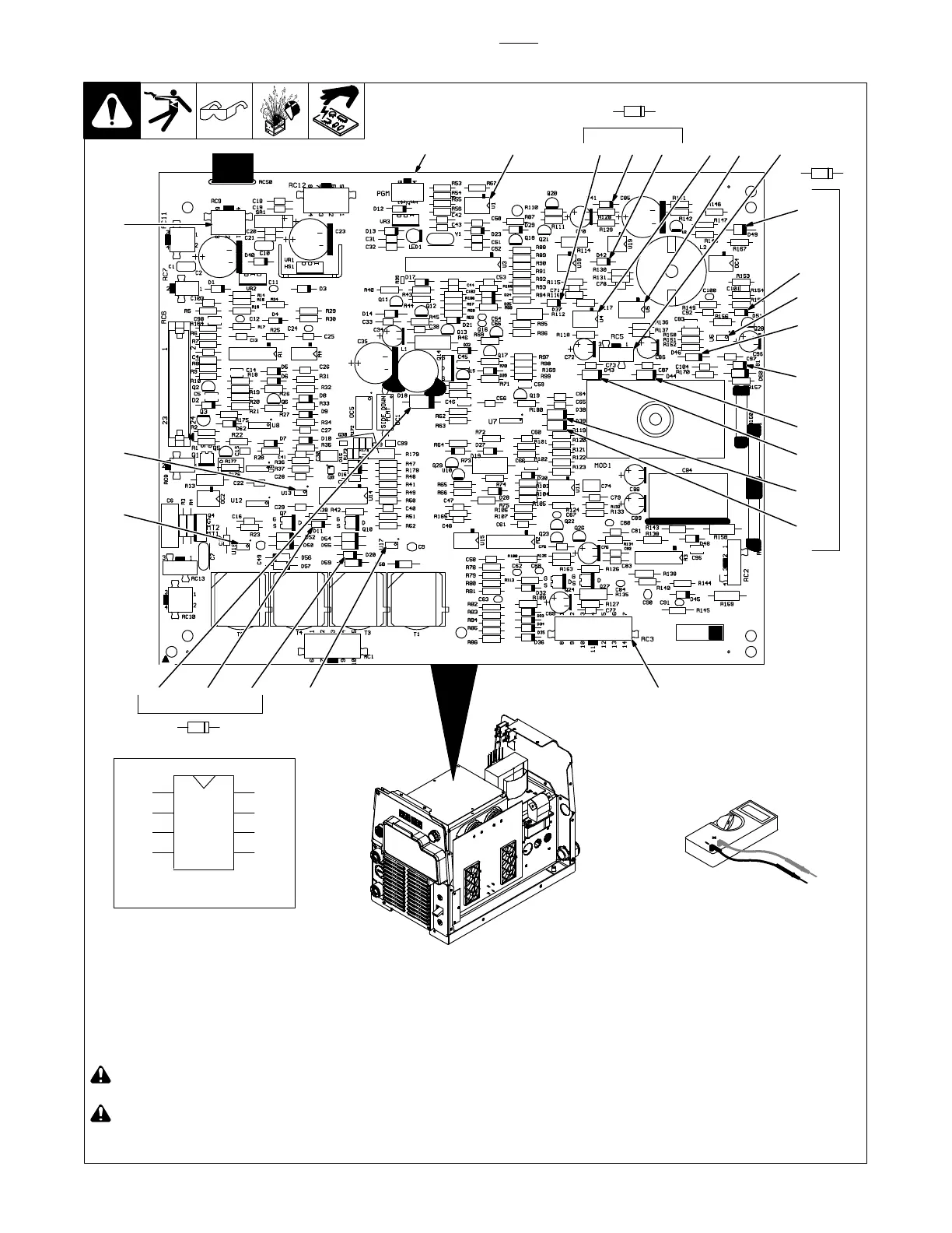
8-21. Control Board PC1 - Power Off Checks
Ref. 276639-A / 907161
! Read and follow safety information
in Section 8-2 before proceeding.
! Wear an earth grounded wrist
strap when performing power off
checks. Remove wrist strap before
performing any checks or proce-
dures with power applied to the
machine.
Remove all plugs from PC1 before
testing.
1 Control Board PC1
Check all measurements for PC1.
If any measurements failed, replace
PC1.
Test Equipment Needed:
1
2
3
4
8
7
6
5
Pin sequence of IC chips.
D39
D38
D43
KA
D44
KA
1
RC3
RC9
U17
U16
U13
RC5U5U4
U1
D61
D46
D51
D49
D37 D42D41
D20D11D18
KA
U6
Board layouts are
slightly different
in older units.
 Loading...