Always check unit before applying power (see Sections 8-2 thru 8-11).
TM-246193 Page 54 Invision 352 MPa
Section 8-24. Power Interconnect Board PC2 Test Point Values (Continued)
! High voltage present. The following terminals are used to interconnect the main power circuit with
the primary supply, and with power circuit components not soldered in the pcb. Voltages on this
receptacle can exceed 900 volts DC from chassis (GND).
Receptacle Pin Type Value
AC1 Power Primary AC mains phase 1; line voltage, measure with respect to AC2 or AC3
AC2 Power Primary AC mains phase 2; line voltage, measure with respect to AC1 or AC3
AC3 Power Primary AC mains phase 3; line voltage, measure with respect to AC1 or AC2
L1 Power Input boost inductor; rectified line voltage, measure with respect to (−) bus
L1-L2 Power Common point between input boost inductor and boost IGBT snubber inductor
L2 Power Boost IGBT snubber inductor
HF-XFMR Power High frequency weld power transformer primary
C13 (+) Power (+) Bus; regulated to 940 volts DC with respect to (−) bus
C12 (−) Power (−) Bus; power circuit common
Center Bus Power Bus capacitors center point; regulated to 470 volts DC with respect to (−) bus
Notes
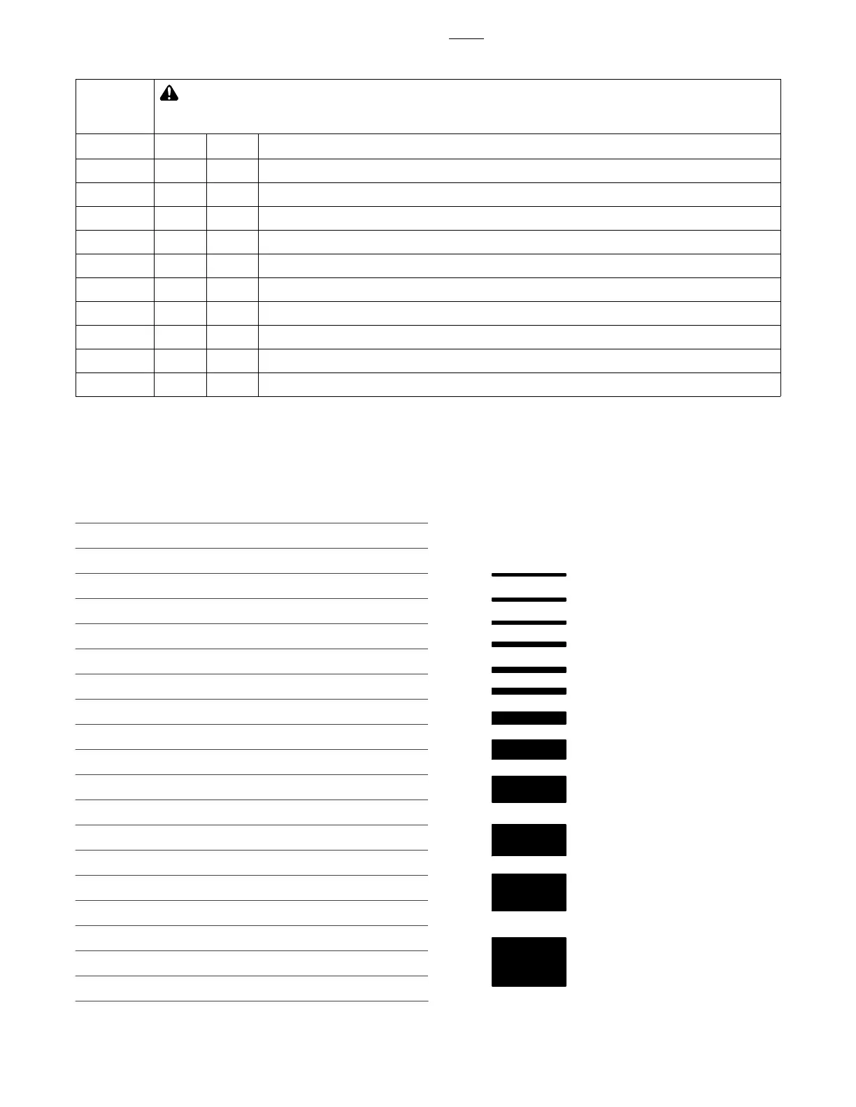
16 Gauge (.063 in)
22 Gauge (.031 in)
24 Gauge (.025 in)
20 Gauge (.037 in)
18 Gauge (.050 in)
14 Gauge (.078 in)
1/8 in (.125 in)
3/16 in (.188 in)
1/4 in (.25 in)
5/16 in (.313 in)
3/8 in (.375 in)
1/2 in (.5 in)
MATERIAL THICKNESS REFERENCE CHART
 Loading...